


Content last revised on September 20, 2026
Preventing Spurious Faults: Input and Brake Chopper Drive Checks for SKD 33/16
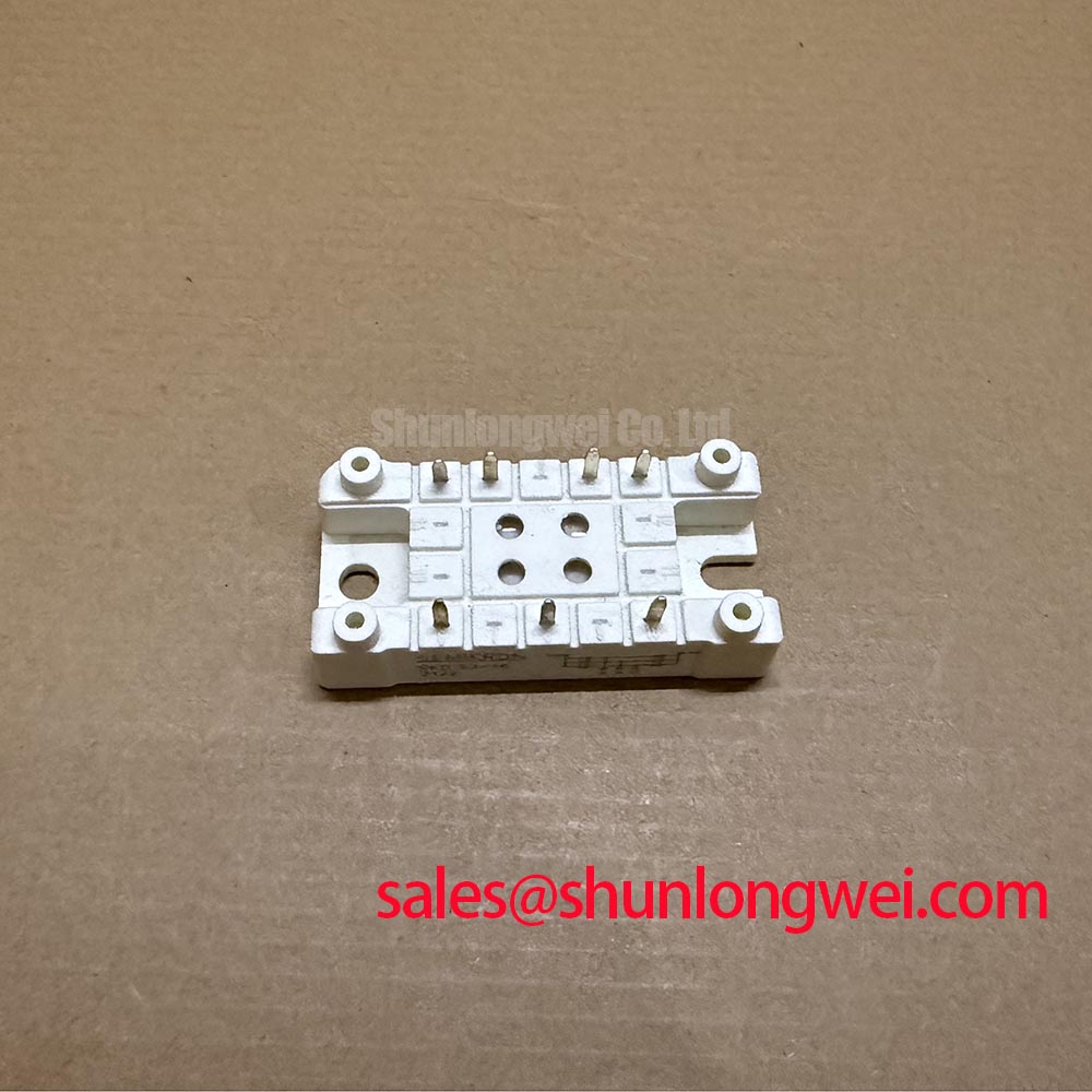
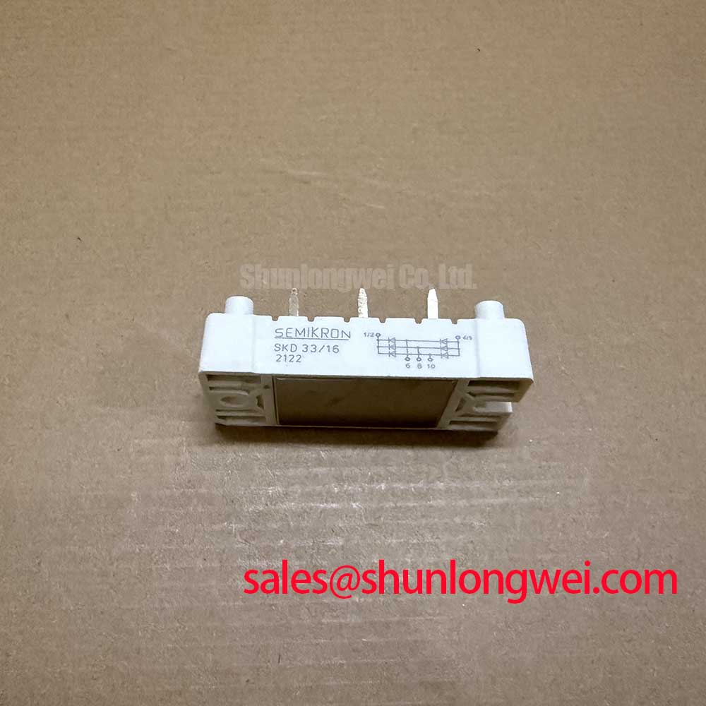
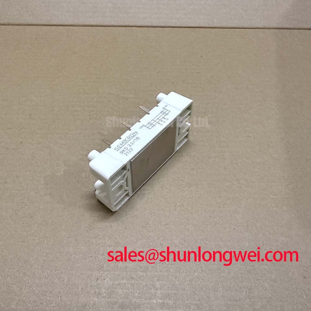
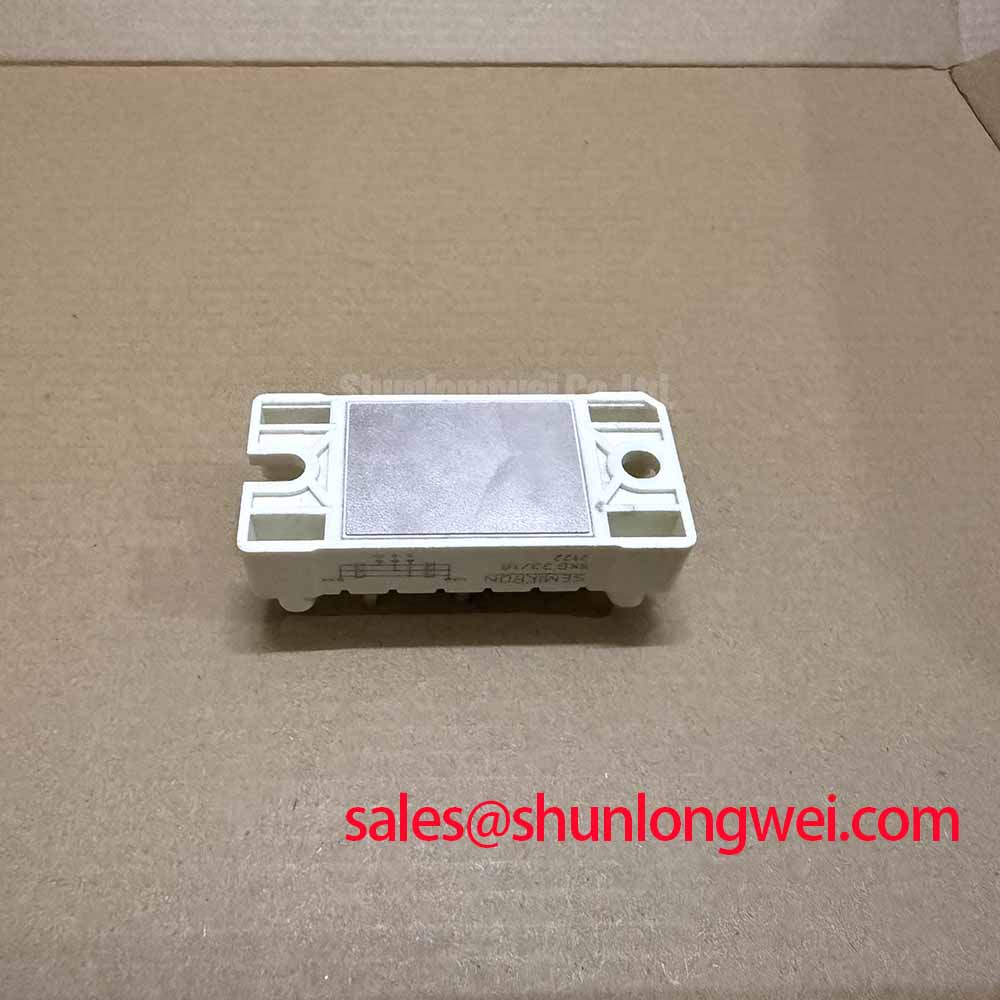
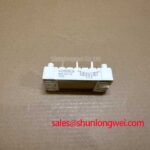
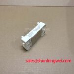
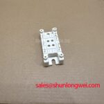
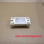
Before fitting an SKD 33/16, isolate the equipment, discharge the DC link according to the machine procedure, and compare the module marking with the service documentation for the required rectifier and brake chopper arrangement. The SKD 33/16 is a Semikron power module combining rectifier diodes with a brake chopper IGBT. Its published ratings identify a 1600 V repetitive peak reverse voltage for the rectifier diodes, 36 A DC output current at Tcase = 80 °C, a 1200 V collector emitter voltage for the brake chopper IGBT, 25 A continuous collector current at Tcase = 80 °C, and 3000 V insulation test voltage. These are Official Datasheet Specifications and should be checked against the original cabinet electrical boundary before replacement.
The first investigation should distinguish an input rectifier problem from a brake chopper control problem. With all power removed and the DC bus confirmed safe, technicians can compare diode conduction paths with the original circuit diagram and inspect power terminals for discoloration, looseness, contamination, or evidence of heat at the cable lug interface. A static resistance check alone cannot confirm dynamic performance, but it can reveal an obvious abnormal path that warrants further examination.
The brake chopper section contains an IGBT, so it must not be approached as though it were a gate triggered thyristor section. No official gate trigger current, gate pulse rise time, holding current, gate charge, or multi pulse firing data has been provided for this model. The existing driver board, its isolation arrangement, its gate wiring, and its protection sequencing must therefore be retained and verified against the equipment manufacturer’s documentation. Engineering Recommendation: inspect the driver output with an appropriately isolated measurement method while comparing it with the known operating sequence of the machine. This helps determine whether a suspected module issue may instead involve a missing enable signal, driver supply fault, interlock condition, or chopper command error.
For equipment used in medium frequency induction melting or hardening furnaces, a brake chopper is commonly assessed as part of DC bus energy management during changing load conditions. That system role does not establish a specific firing waveform or control threshold for the SKD 33/16. The system integrator should verify the DC link voltage, braking resistor network, driver timing, and fault logic in the furnace power supply before energizing a replacement assembly.
⚠️ Maintenance Note: Periodically monitor terminal contact temperature and verify that cooling air passages remain clear before heat related faults develop into unplanned downtime.
Fuse selection and coordination must be based on the machine manufacturer’s protection documentation and the applicable fuse data, including its pre arcing and clearing behavior. No fuse I²t value is stated in the provided SKD 33/16 specifications, so an exact fuse coordination figure should not be assigned to this module without the relevant source data. Design Consideration: protective devices should be assessed for both the rectifier current path and the energy released by a DC link fault, with the final decision confirmed by the system protection engineer.
Transient Dynamics and Electrical Design: DC Link Behaviour Around SKD 33/16
The SKD 33/16 rectifier section converts the incoming AC supply into a DC output for the surrounding power stage, while the integrated brake chopper IGBT is evaluated separately as a controlled path associated with the DC link. The stated rectifier limit is VRRM = 1600 V, and the stated DC output current is ID = 36 A at Tcase = 80 °C. These values define the published electrical identity of the diode section; they do not by themselves define the permissible AC supply, transformer secondary voltage, overload profile, capacitor bank, or furnace power rating.
Firing delay angle analysis applies to controlled rectifier topologies that use thyristors or equivalent controllable input devices. The diode bridge within the SKD 33/16 does not have a firing angle adjustment. If a furnace cabinet includes phase controlled devices upstream of this module, their delay angle, reactive power demand, and resulting DC bus behavior belong to the complete power supply design rather than to the SKD 33/16 diode characteristics. Service personnel should identify the actual upstream topology before changing controller parameters.
In practical troubleshooting, measure the incoming phase balance, observe the DC link under the approved service procedure, and compare the waveform behavior with a known healthy system where available. Excessive ripple, phase loss, connector heating, or unexpected bus movement can arise from several locations, including supply contacts, transformer connections, capacitors, control circuits, or the rectifier path. The correct approach is to verify each interface rather than assign one electrical symptom to a single cause.
The brake chopper IGBT is officially rated at VCES = 1200 V and IC = 25 A continuous at Tcase = 80 °C. Engineering Recommendation: keep the power loop physically compact where the original equipment layout permits, because parasitic inductance can contribute to voltage overshoot during switching. Peak voltage margins should be verified at the DC link during controlled switching tests by the system engineer. Any MOV, snubber, clamp, braking resistor, or cable filter already used in the cabinet should be evaluated as part of the complete protection network, not treated as an optional add on based only on the module voltage rating.
When comparing repair options, the SKD82/18 should be evaluated through a documented comparison of electrical ratings, circuit function, physical interface, cooling arrangement, and original driver compatibility. A different current or voltage designation does not establish interchangeability. For systems where a lower rated bridge module is being reviewed in a related rectification position, the SKD 25/14 provides a separate reference point, subject to the same circuit level verification.
SKD 33/16 Circuit Protection and Reliability: Rectifier Commutation Checks
The rectifier diodes in the SKD 33/16 are specified for 1600 V repetitive peak reverse voltage. During commutation, diode recovery behavior interacts with transformer leakage inductance, supply impedance, DC link capacitance, wiring layout, and the operating current waveform. The provided official information does not state reverse recovery peak current, reverse recovery charge, recovery time, softness factor, or EMC performance. These values must not be inferred from the voltage and current ratings.
Design Consideration: where switching transients or noise are suspected, capture relevant voltage and current waveforms using correctly rated and safely connected instruments, then compare them with the machine’s normal operating signature. This is more reliable than assuming that a particular recovery characteristic is present. Cable routing, power terminal contact quality, enclosure bonding, and the condition of existing suppression components can all influence observed ringing and interference.
The 3000 V insulation test voltage is an Official Datasheet Specification for the module insulation test. It should not be interpreted as a complete system insulation coordination result, a site safety certification, or an assurance of long term insulation performance in every environment. Condensation, conductive dust, contaminated heatsinks, damaged cables, and degraded creepage paths elsewhere in a cabinet can defeat system insulation even when the module itself remains within its published specification.
For furnace power equipment exposed to airborne dust, thermal cycling, and intermittent operation, planned inspection should include the power terminal surfaces, insulation barriers, fan operation, cabinet seals, and signs of moisture accumulation. Allow the cabinet environment to stabilize before high voltage testing after a cold shutdown where condensation is possible. The objective is to prevent misleading measurements and avoid energizing a damp power assembly.
Industry documentation on IGBT terminology and test context can be consulted through IEC 60747 9 Semiconductor Devices, Discrete Devices, IGBTs. This reference supports disciplined interpretation of IGBT related electrical characteristics but does not replace the equipment specific service procedure or the SKD 33/16 product documentation.
Do not assign an independent CISPR or EN 55011 EMC compliance claim to the SKD 33/16. EMC behavior is determined by the complete assembly, including control board layout, filters, shielding, grounding, enclosure construction, cable routing, load connections, and operating conditions. When interference occurs after service work, inspect restored cable screens and bonding straps before changing circuit values.
Thermal Contact Control for SKD 33/16 in Continuous Industrial Service
Start thermal maintenance by cleaning the heatsink mating surface and checking that the module sits flat before fasteners are tightened. The published current ratings for the SKD 33/16 are explicitly stated at Tcase = 80 °C: 36 A for the DC output current of the rectifier diodes and 25 A for continuous collector current of the brake chopper IGBT. These ratings make case temperature a critical inspection point in a working cabinet.
No official junction to case thermal resistance, thermal impedance curve, baseplate construction detail, mounting screw size, mounting torque, or thermal interface thickness has been supplied for this model. It would therefore be inaccurate to publish a specific torque or thermal paste thickness as an SKD 33/16 factory requirement. Design Consideration: use the mounting method and tightening sequence specified by the original equipment documentation, apply thermal interface material consistently where the assembly calls for it, and avoid uneven clamping that could compromise surface contact or mechanically stress the module.
A module may experience elevated case temperature because of restricted airflow, aged thermal material, an uneven heatsink surface, loose terminal hardware, a loaded DC link, or changing process duty. Thermal diagnosis should separate these possibilities. Compare fan condition, filter cleanliness, heatsink temperature distribution, terminal temperature, and operating current with the machine’s established maintenance baseline. Where thermal imaging is available, it can identify nonuniform heating that should be examined before a replacement module is placed under full process load.
In induction melting and hardening power supplies, verify that cooling hardware and airflow are restored before returning the equipment to sustained operation. The module ratings do not establish a complete cooling requirement for a particular furnace cabinet. The system engineer should validate case temperature and electrical loading under the actual process cycle, including periods of changing load and braking activity.
For a broader framework covering power semiconductor ratings, interfaces, and application level comparison criteria, consult the Power Semiconductor Selection Guide. Semikron Danfoss also provides product family context through its SEMITRANS industry standard IGBT information; confirm the exact SKD 33/16 configuration against the relevant product documentation before making a service decision.