Content last revised on October 17, 2026
SKD116-16-L105 Thermal-Electrical Optimization: Short-Circuit Withstand Limits and Practical Tuning
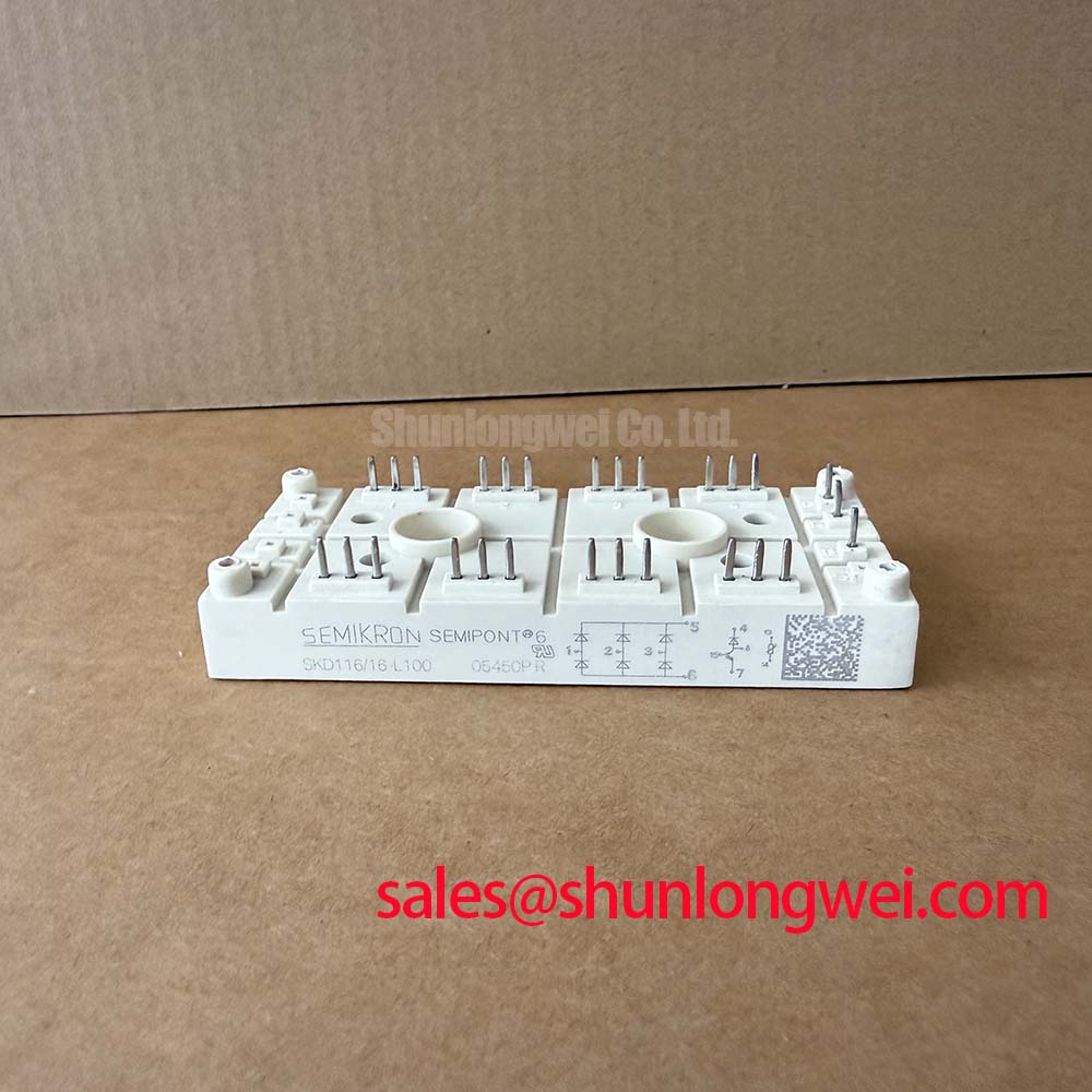
At the service bench, isolate the converter, discharge the DC link, and compare the rectifier terminals with the original wiring before applying any test voltage. The identified part is the Semikron SKD116-16-L105, specified as a 1600 V bridge rectifier module with a listed rated current of 116 A and a Semipont package. These are official supplied product parameters for replacement screening; actual operating limits remain dependent on the complete thermal, protection, and switching arrangement.
For a grid-tied Static Var Compensator or thyristor-switched capacitor assembly, confirm the rectifier position in the power path before comparing terminals. Check polarity markings, busbar orientation, insulation clearances, heat-sink contact, and the original fuse coordination record. A bridge rectifier does not provide a gate-firing interface. Any pulse-transformer firing circuit belongs to an upstream controlled thyristor stage or another gated device, so its timing and gate-current requirements must not be assigned to the SKD116-16-L105 without a matching circuit diagram.
Short-circuit coordination starts with the semiconductor fuse clearing record and the module’s permitted surge and thermal limits. The service engineer should compare the fuse I²t clearing energy with the applicable rectifier withstand data for the installed operating temperature and fault path. The comparison must include the actual fuse class, prospective fault current, bus inductance, and clearing time rather than relying on the module’s nominal current rating alone.
For a failed SVC rectifier, document whether the fuse operated before the semiconductor junction suffered secondary damage. Inspect the fuse holder, busbar joints, terminal faces, and heat-sink interface for evidence of a high-resistance connection or uneven pressure. The Semipont package requires mechanical installation that preserves flat, stable thermal contact. Use the original assembly specification for mounting hardware and torque, then verify that the pressure arrangement remains uniform after thermal cycling.
Long motor or auxiliary feeder cables can introduce transmission-line reflection into a converter installation. When a rectifier feeds a switching stage connected through a long cable, the resulting transient can increase the voltage seen by downstream semiconductor devices. A design consideration is to minimize the high-current loop area and control the return path, while the system engineer verifies peak voltage during switching tests against the installed DC-link and insulation limits.
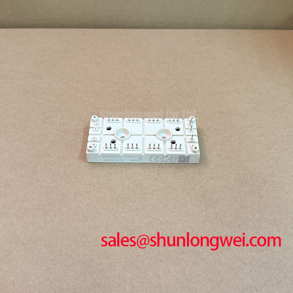
For replacement screening, compare the original terminal layout and busbar geometry with SKD116/18-L75 as a separate Semikron family reference. This is a neutral compatibility check, not a prescriptive substitute decision. The selected device must match the circuit’s voltage, current, mechanical, thermal, and protection requirements.
Benchtop Waveform Tuning: Mitigating Stress via Pulse-Transformer Isolated Firing Circuits
Before probing any firing waveform, identify which devices in the SVC actually require gate control. The supplied identification describes the SKD116-16-L105 as a bridge rectifier module, so pulse rise time, gate current, back-porch holding current, and multi-pulse firing schemes apply to a separate controlled thyristor stage when present. Treating the rectifier as a gated device could lead to incorrect wiring or an invalid replacement assessment.
In the controlled stage, inspect the pulse-transformer secondary at the device terminals rather than only at the driver output. Look for pulse distortion, unequal channel amplitude, excessive ringing, and loss of the holding portion after the initial firing edge. A measured gate-current rise requirement, including any target such as diG/dt greater than 1 A/µs, must come from the applicable thyristor data and gate-driver design, not from the SKD116-16-L105 identification.
The isolated firing circuit should be checked with the power stage disabled first. Confirm transformer polarity, secondary return routing, insulation integrity, and the absence of unintended common-mode paths. Where a front-end rectifier supplies the control or auxiliary power architecture, the SKB 30/12 A1 may be evaluated as a related system-level rectifier reference, subject to the original topology and electrical ratings.
Pro Tip: Keep the pulse-transformer wiring physically separate from high-current commutation paths and verify the final waveform at the controlled device terminals after the mechanical assembly is complete.
Field Diagnostics and Commissioning: Evaluating Post-Surge Reverse Voltage Blocking
After a surge event, evaluate reverse-voltage blocking only after the module has been isolated from the bus and the surrounding protection network has been inspected. The key checks are terminal polarity, heat-sink condition, fuse status, snubber condition, and any evidence of arc tracking or localized heating. A low-resistance reading by itself does not identify the failed element; compare all relevant conduction paths with a known-good circuit and use controlled instrumentation.
The sinusoidal 10 ms half-cycle surge rating, commonly identified as ITSM for controlled or rectifying semiconductor devices, must be taken from the applicable Semikron data for the exact construction and test conditions. Do not infer that value from the 1600 V voltage rating or the listed 116 A current rating. Before reverse voltage is reapplied, verify that the surge protection network, fuse coordination, busbar spacing, and thermal path are restored to the intended system condition.
Commissioning should proceed with staged voltage application and monitored current, temperature, and waveform behavior. If a long cable connects the converter to the equipment, observe the switching node at the receiving end as well as at the cabinet, because reflected transients can change the stress seen by the power assembly. The engineering objective is to suppress parasitic-inductance-driven turn-off overshoot through busbar layout and damping selection, with final margins established by system testing.
For additional power-semiconductor integration guidance, consult the Power Electronics Masterclass and the Semikron-Danfoss Power Electronics and Modules Official Hub. These references support the broader evaluation of switching stress, thermal interfaces, and protection coordination around the installed bridge rectifier.