

Content last revised on October 28, 2026
MDQ60-16 Identification and Replacement Assessment
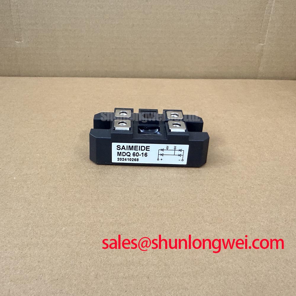
With the rectifier isolated and stored energy discharged, trace the AC and DC conductors against the equipment schematic before disconnecting the MDQ60-16. Record terminal markings and busbar orientation so that the replacement assessment starts with the actual circuit connections rather than the package outline.
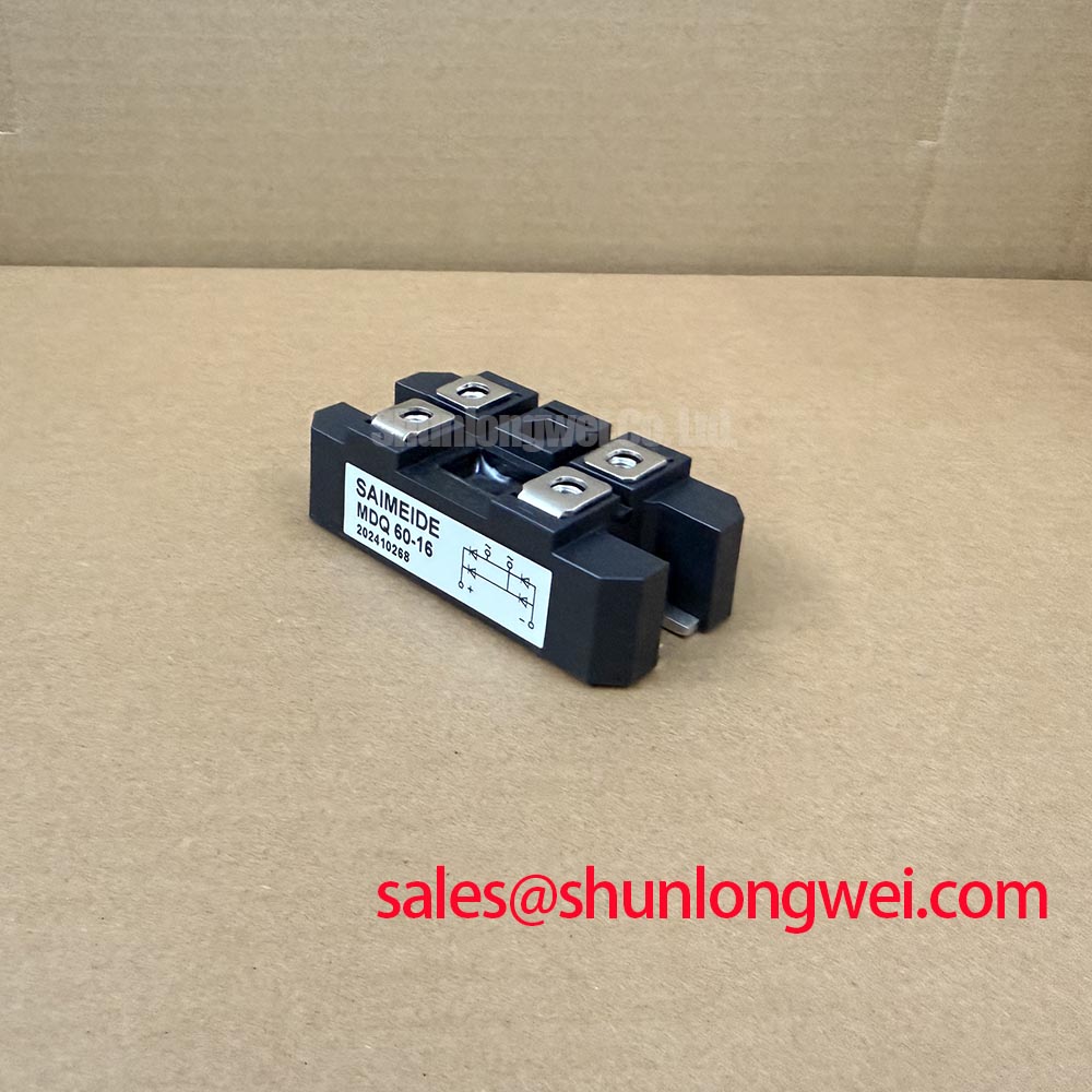
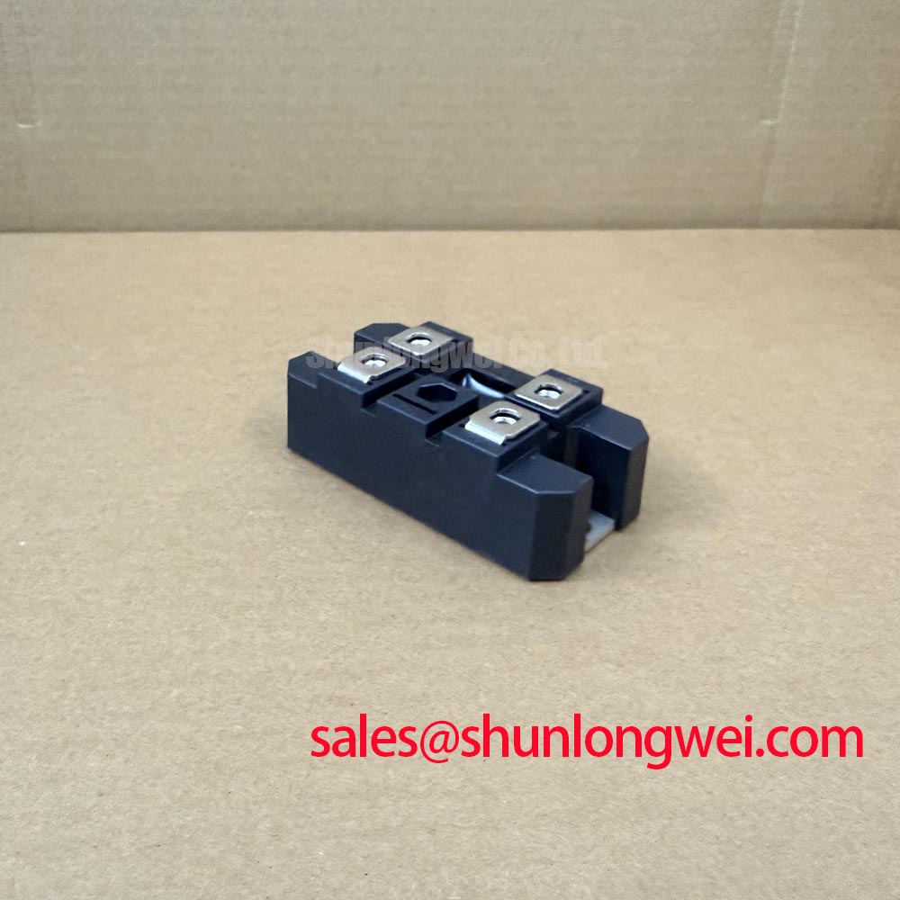
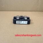
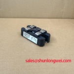
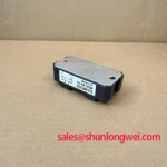
The MDQ60-16 is a Bridge Rectifier Module with listed ratings of 1600 V and 60 A and the package designation Three-Phase Rectifier Case. These identifiers establish the initial sourcing boundary. For replacement assessment, consult the device datasheet for the internal circuit, terminal drawing, rating conditions, surge withstand, thermal resistance, and fastening requirements; the case designation alone does not establish the internal bridge arrangement.
Benchtop Waveform Tuning: Mitigating Stress via Interphase Transformer Current Balancing on MDQ60-16
Compare branch-current waveforms at equivalent measurement points before changing an interphase transformer connection. As a Design Consideration, current imbalance should be assessed alongside transformer secondary voltages, conductor resistance, connection integrity, and cooling conditions. A higher branch current does not, by itself, identify the transformer as the cause.
In general rectifier architecture, a six-pulse bridge rectifies a three-phase supply; a twelve-pulse arrangement combines appropriately phase-shifted bridge groups. Where those groups operate in parallel, an interphase transformer can support their intended current-sharing arrangement. This describes system topology, not a confirmed internal configuration or kiloampere output capability of the MDQ60-16. Its 60 A rating must remain tied to the manufacturer's operating conditions.
As an Engineering Recommendation, keep parallel branch conductors electrically comparable and assess their current sharing under controlled load changes, with simultaneous measurements where practical. Check commutation-related voltage excursions at the module terminals against the applicable device limits. Transformer connections and instrument reference points should follow the equipment schematic, not an assumed bridge layout.
A high-current green hydrogen electrolyzer DC power rectifier is one potential compatibility assessment context, subject to the complete power-stage design. When comparing the VUO192-16NO7, compare circuit topology, terminal assignments, rating conditions, cooling requirements, and mounting geometry rather than treating it as a direct substitute. The MDS500-12 can likewise be considered separately when reviewing a front-end or auxiliary rectification stage; its circuit role must come from that stage's schematic.
MDQ60-16 Operational Boundaries: Ensuring Uniform Heatsink Contact Pressure
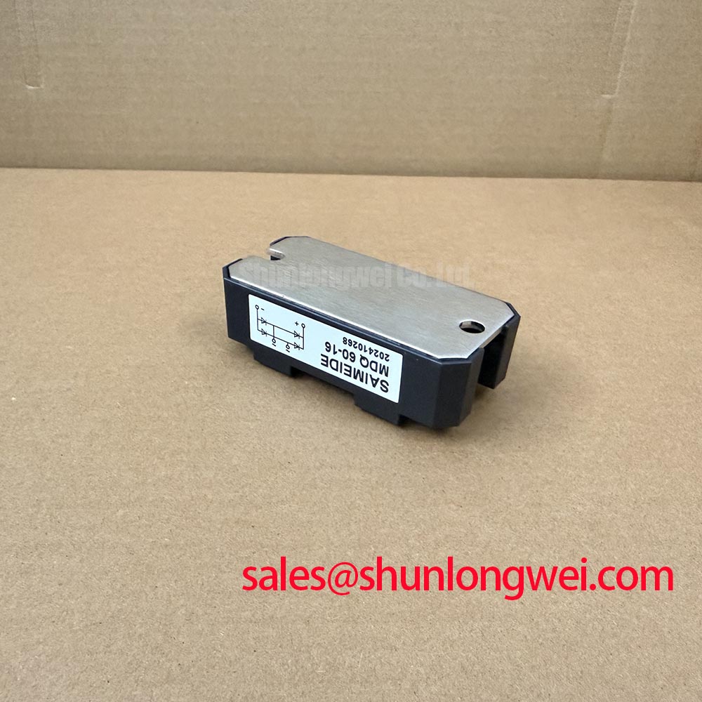
Inspect the mating heatsink surface for raised burrs, contamination, and uneven contact before fastening the module. As a Design Consideration, clamping pressure should establish consistent thermal contact without bending the package or loading the electrical terminals through misaligned busbars. Baseplate material is not established by the supplied specifications.
Thermal assessment should connect conduction losses, junction-to-case thermal resistance, interface resistance, and measured case temperature. The datasheet's junction-to-case value belongs to its stated heat-flow path and test conditions; it is not the complete junction-to-ambient thermal resistance. An unusually hot terminal warrants checking connection resistance as well as the cooling path.
As an Engineering Recommendation, follow the specified fastening sequence and torque, inspect thermal-interface spreading during assembly validation, and support conductors independently of the module. Surface temperature measurements are most useful when their locations and load conditions remain consistent. Do not assign a generic mounting torque or interface thickness to this package.
DC-link capacitor heating also affects the surrounding thermal environment. Film Capacitors in High Ripple Current DC-Link Applications provides general background on film-capacitor construction and applications, not MDQ60-16 qualification evidence. The system discussion in Peak Efficiency in Solar and Energy Storage offers related converter context; neither resource establishes this module's service life.
Assembly Integrity & Layout Architecture: Fuse Coordination for MDQ60-16
Compare the semiconductor fuse's total clearing I²t with the rectifier's applicable surge-withstand data at the prospective fault current and recovery voltage. As a Design Consideration, fuse pre-arcing I²t alone does not represent the complete fault let-through, and the normal current rating does not establish short-circuit survival.
| Coordination item | Required comparison |
|---|---|
| Fuse total clearing I²t | Device withstand under compatible waveform, voltage, and temperature conditions |
| Peak let-through current | Applicable non-repetitive surge-current limit and pulse duration |
| Breaking capacity | Prospective fault current and circuit voltage at the installation point |
| Post-fault condition | Equipment-specific inspection and acceptance criteria |
The Type 2 coordination concept in IEC 60947-4-1 concerns contactors and motor starters; it does not independently certify a rectifier-and-fuse assembly. Sub-cycle clearing and freedom from destructive damage require evidence for the complete protective arrangement, not an inference from the 1600 V rating.
Practical reminder: Verify DC-link discharge before touching terminals or changing current-measurement connections. During reassembly, preserve the equipment's specified creepage and clearance distances, remove conductive debris, and check terminal seating before restoring power. After a fault, assess the fuse, rectifier, busbars, and insulation under the equipment's approved inspection procedure rather than re-energizing solely because the fuse has been replaced.