

Content last revised on September 24, 2026
VUO192-16NO7 Circuit Protection & Reliability: Assessing Current and Thermal Stress
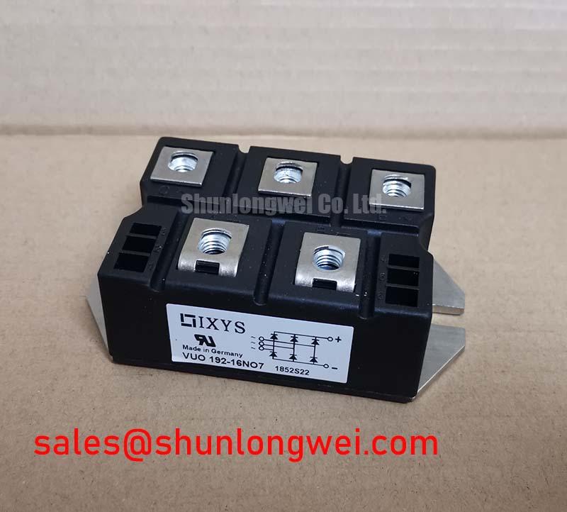
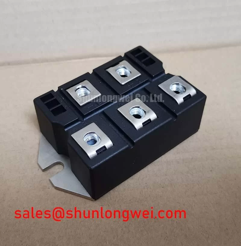
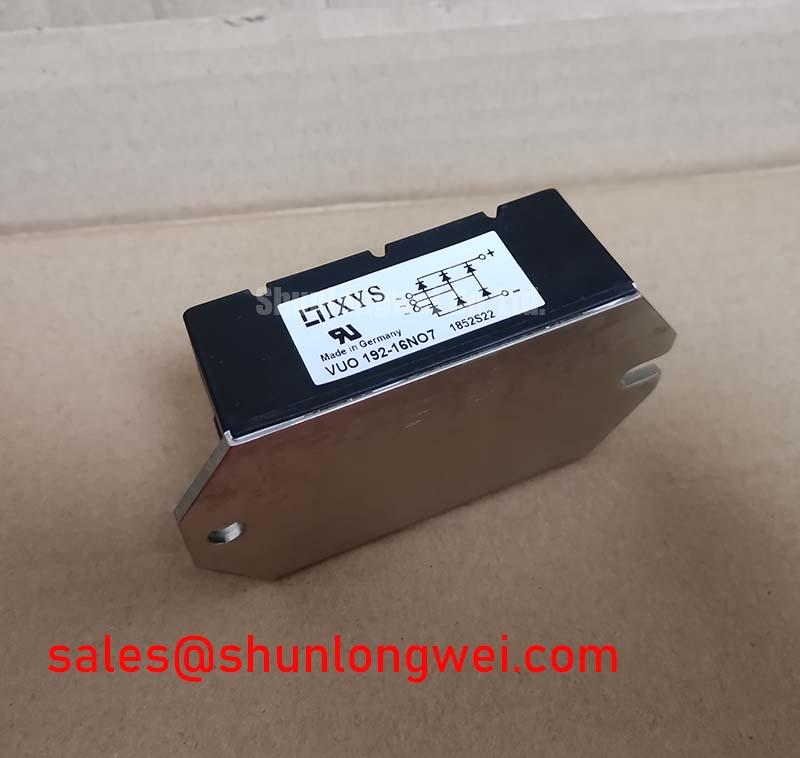
With the converter isolated and discharged, begin by checking the VUO192-16NO7 terminal arrangement against the original wiring diagram, then use the meter’s diode function to compare each accessible rectifying path for consistency before reconnecting the power cables. This IXYS unit is a Bridge Rectifier Module rated at 1600 V and 192 A as an Official Datasheet Specification. Those ratings define the device identity; they do not establish the allowable fault energy, thermal interface condition, or protection coordination of a particular cabinet.
Gate trigger current, holding current, firing pulses, and firing delay angle are not applicable characteristics for a diode bridge rectifier module. If a field drawing labels control wiring near this device, trace it carefully: the wiring may belong to an upstream controlled rectifier, contactor logic, measurement circuit, or another semiconductor assembly. For protection coordination, the system integrator should obtain the applicable semiconductor fuse time current curve and total clearing I²t data, then compare them with the protected circuit and the original equipment documentation. No device melt I²t or fuse coordination table is stated in the supplied official data for this model.
⚡ Field Alert: Isolate all stored DC link energy before removing terminal hardware, and tighten connections only to the equipment maker’s specified fastener torque.
VUO192-16NO7 Thermal and Electrical Optimization: Practical Rectifier Assessment
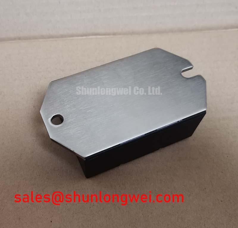
Confirm that the module mounting surface is clean, flat, and free from old compound ridges before assessing a suspected thermal problem. Use an even, thin thermal interface layer where the original assembly requires it, and inspect busbar contact faces for discoloration, looseness, or evidence of heat cycling. The 1600 V voltage rating and 192 A current rating are Official Datasheet Specifications, but they should not be converted into a site specific continuous load prescription without the original thermal design and duty cycle.
A diode bridge has no controllable firing angle. Where an AC to DC supply uses phase controlled rectification ahead of, or alongside, a diode bridge, firing angle adjustment is handled by the controlled rectifier subsystem rather than by the VUO192-16NO7. Design Consideration: a larger phase delay can change input displacement factor and reactive power demand, so technicians should verify the actual converter topology, line waveform, DC output waveform, and control board signals before changing any timing parameter.
For a high current green hydrogen electrolyzer DC power rectifier, this module can be evaluated as part of the passive rectification stage only when terminal layout, voltage class, current duty, cooling arrangement, and protection architecture match the existing equipment. A SKD82/18 should be treated as a separate part for documented compatibility review rather than an automatic replacement.
VUO192-16NO7 Operational Boundaries: Evaluating Reverse Recovery Charge Limits
During commissioning, inspect the AC input and DC output with correctly rated instruments while comparing waveforms with a known healthy channel or the equipment service documentation. Reverse recovery current and recovery time can influence commutation stress, cable ringing, and conducted noise in a rectifier circuit, but no numerical reverse recovery charge, peak recovery current, or recovery time values are included in the supplied official specifications for the VUO192-16NO7. Those figures must not be assumed from the voltage and current ratings alone.
Design Consideration: minimize unintended inductive loop area between the bridge, fuse, DC bus, and any suppression network when investigating commutation overshoot. The system engineer should validate observed peak voltage against the DC link and device ratings during switching tests. If the cabinet includes active front end equipment, its operation should be assessed separately from the diode bridge. The Vienna rectifier topology is an active three phase power factor correction topology and should not be treated as electrically interchangeable with a passive bridge module.
When abnormal noise, heating, or repeated fuse operation appears, inspect the complete current path rather than assigning a single cause to the module. Relevant checks include supply phase balance, busbar joint condition, snubber integrity where fitted, cooling airflow or liquid circuit condition, and waveform comparison under the permitted operating procedure.
Field Diagnostics & Commissioning: Fuse Total Clearing I²t versus Device Melt in VUO192-16NO7 Topologies
For a dead short investigation, first document the installed fuse part number, fuse position, upstream disconnect arrangement, bridge terminal condition, and visible state of the DC bus before replacing parts. Total clearing I²t includes the energy passed during fault detection and interruption, while semiconductor withstand capability is device specific. Since no official I²t withstand value or surge current specification has been supplied for the VUO192-16NO7, a numerical coordination claim cannot be made for this product page.
Engineering Recommendation: use the original equipment manufacturer’s protection study, fuse documentation, and rectifier schematic to confirm that the selected fuse protects the intended branch under prospective fault conditions. Verify whether a failed fuse followed a bridge fault, downstream DC load fault, busbar insulation issue, or an external supply event. Replacing the bridge without resolving the initiating condition can leave the repaired power rectifier exposed to the same stress.
For controlled rectifier cabinets that share a DC bus with diode bridge sections, commissioning should include confirmation of command sequencing, isolation states, and measured voltage polarity before energization. Practical troubleshooting references for drive and pulse related subsystems are available in Precision Gate Drive Design; their gate drive guidance applies to controlled semiconductor stages, not to the passive diode paths within this bridge rectifier module.