The Unseen Engine: Why IGBTs are Indispensable for High-Power Wireless EV Charging
As the automotive industry pivots aggressively towards electrification, the convenience of wireless charging is no longer a futuristic concept but an emerging engineering reality. While we are accustomed to wirelessly charging our smartphones, scaling this technology to power electric vehicles (EVs) presents a monumental challenge. The core of this challenge lies in efficiently managing immense power levels, a task where the Insulated Gate Bipolar Transistor (IGBT) module proves to be the unsung hero. This article delves into the critical role of IGBTs in high-power wireless charging piles, exploring the technical demands, selection criteria, and future trends that engineers and procurement managers must navigate.
The Convenience Revolution vs. The Power Challenge
The vision is simple: park your EV over a charging pad and walk away. No heavy cables, no connectors, just seamless power transfer. But translating this vision from a 15W phone charger to a 50kW, 100kW, or even higher-power EV charger requires a profound leap in power electronics design.
The Pain Point: Moving from Low-Power Gadgets to High-Power Vehicles
Low-power wireless charging operates at low currents and voltages, where component stress is minimal and efficiency is less critical. In contrast, high-power Wireless Power Transfer (WPT) for an EV inverter system involves handling hundreds of amperes and volts. Every percentage point of efficiency loss translates into significant heat generation, posing severe thermal management challenges and increasing operational costs. This is where the power switching components become the make-or-break element of the entire system.
Why Megawatts Matter: The Engineering Hurdles in Scaling Up WPT
A typical high-power WPT system for EVs operates by generating a high-frequency alternating magnetic field in a transmitting coil embedded in the ground. A receiving coil in the vehicle captures this field and converts it back into electrical energy to charge the battery. The heart of this system is the high-frequency inverter, which must chop a high DC voltage into a high-frequency AC waveform with extreme precision and minimal energy loss. This is the domain where robust, high-performance power semiconductors are essential.
Deconstructing the Wireless Charging Pile: Where IGBTs Take Center Stage
To appreciate the role of IGBTs, it’s crucial to understand their position within the WPT architecture. The system is a multi-stage power conversion chain, and the IGBT-based inverter is its most critical link.
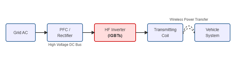
The Core Architecture: From Grid to Vehicle Battery
A typical wireless charging pile performs several conversions:
- AC/DC Rectification & PFC: The incoming grid AC is converted into a stable high-voltage DC bus (e.g., 400V or 800V). Power Factor Correction (PFC) ensures grid stability.
- DC/AC High-Frequency Inverter: This is the core stage. The high-voltage DC is converted into high-frequency AC (typically 20-150 kHz) by a power inverter. This stage determines the system’s efficiency and power output.
- Resonant Tank & Transmitting Coil: The high-frequency AC drives a resonant circuit connected to the transmitting coil, generating the magnetic field for power transfer.
The High-Frequency Inverter: The Heart of the System
The inverter, usually in a full-bridge or half-bridge topology, is responsible for creating the high-frequency current needed for wireless transfer. Its performance directly dictates the overall system efficiency. The switches in this inverter must handle the full power of the system, turning on and off tens of thousands of times per second. This demanding role is perfectly suited for high-voltage IGBT modules.
The IGBT’s Role: Precision High-Speed Switching at High Voltage and Current
In this inverter, IGBTs act as high-speed electronic switches. They take the stable DC voltage from the bus and, based on signals from a microcontroller, switch it on and off rapidly to create an AC waveform at the desired frequency. Their ability to handle high breakdown voltages (1200V and above) and large currents (hundreds of amps) makes them ideal for this high-power application, far exceeding the capabilities of standard MOSFETs in this power class.
Critical IGBT Parameters for High-Performance Wireless Charging Systems
Selecting the right IGBT is not merely about matching voltage and current ratings. For a high-frequency WPT application, a nuanced understanding of dynamic and static parameters is crucial for achieving high efficiency and reliability.
Balancing Act 1: Low VCE(sat) for Conduction Efficiency
The collector-emitter saturation voltage, VCE(sat), determines the power lost when the IGBT is fully on (conducting current). A lower VCE(sat) means less heat generated during the conduction phase. In a system transferring 50kW, even a 0.1V reduction in VCE(sat) can save hundreds of watts of power, simplifying thermal design.
Balancing Act 2: Fast Switching Speed (Eon/Eoff) for Reduced Losses
Every time an IGBT turns on (Eon) or off (Eoff), a small amount of energy is lost. In a high-frequency system, these switching losses can become the dominant source of heat. Modern IGBTs, like those with trench-gate field-stop technology, are optimized for fast switching to minimize these losses, which is critical for WPT systems operating above 20 kHz.
The Non-Negotiable: Robust Short-Circuit Withstand Time and SOA
The operating environment for EV charging can be unpredictable. A foreign metal object on the charging pad or a sudden misalignment can cause short-circuit conditions. The IGBT must have a sufficient short-circuit withstand time (typically 5-10 µs) and a robust Safe Operating Area (SOA) to survive these fault events without catastrophic failure.
The Silent Killer: Thermal Performance (Rth) and Its Impact on Reliability
All the losses discussed above manifest as heat. The IGBT module’s thermal resistance from junction to case (Rth(j-c)) dictates how efficiently this heat can be extracted. A low Rth is vital for keeping the semiconductor junction temperature within safe limits, directly impacting the module’s lifespan and the system’s overall reliability. Effective thermal management is a cornerstone of high-power design.
Case Study: Selecting an IGBT for a 50kW Wireless EV Charging Station
Problem:
An engineering team is tasked with designing a 50kW wireless EV charging station with a target efficiency of over 95%, operating at a resonant frequency of 85 kHz. The DC bus voltage is 750V. The system must be robust enough for public deployment.
Solution: A Step-by-Step Selection Process
The team follows a structured approach:
- Voltage and Current Calculation: With a 750V DC bus, a 1200V-rated IGBT is chosen to provide sufficient safety margin against voltage spikes. The peak current is calculated to be over 100A, so a module rated for at least 200A is selected for derating and reliability.
- Switching Frequency vs. Loss Analysis: At 85 kHz, switching losses are significant. The team compares datasheets of several IGBTs, focusing on Eon, Eoff, and recovery energy (Erec) of the anti-parallel diode. They prioritize modules specifically designed for high-frequency operation. Advanced technologies like Infineon’s TRENCHSTOP™ IGBT7 offer lower switching losses compared to older generations.
- Thermal Simulation: Using the calculated conduction and switching losses, a thermal simulation is performed. The team selects a module with low Rth(j-c), such as the SKM400GAR12T4, to ensure the junction temperature remains below 125°C under worst-case ambient conditions with a reasonably sized heatsink.
- Gate Drive Optimization: A robust gate driver circuit is designed with a Kelvin emitter connection to minimize the impact of stray inductance, ensuring clean and fast switching.
Result:
By carefully selecting a modern, high-frequency 1200V IGBT module and optimizing the surrounding circuit, the team achieves a peak inverter efficiency of 96.5%. The stable thermal performance under full load confirms the design’s long-term reliability, meeting the project’s demanding requirements.
The Future Landscape: IGBTs vs. SiC in the High-Power Charging Arena
The conversation about high-power switching is incomplete without mentioning Silicon Carbide (SiC) MOSFETs. SiC offers superior switching speeds and lower losses, especially at higher frequencies. However, the choice is not always straightforward.
The Technology Showdown: A Comparative Analysis
| Parameter | IGBT Modules | SiC MOSFET Modules |
|---|---|---|
| Switching Frequency | Good (up to ~100 kHz) | Excellent (>100 kHz) |
| Conduction Loss (VCE(sat) / Rds(on)) | Lower at very high currents | Lower at light to medium loads |
| Voltage Rating | Mature up to 6.5kV | Mature up to 1.7kV, higher voltages emerging |
| Cost | Cost-effective, mature technology | Higher initial cost, but decreasing |
| Ruggedness (SCWT) | Excellent, inherently robust | Good, but requires very fast protection circuits |

Why IGBTs Still Dominate in Cost-Sensitive, High-Power Applications
For power levels above 30-50kW, IGBTs like the powerhouse FZ3600R17HE4 often present a more compelling cost-performance ratio. Their proven reliability, robustness under fault conditions, and mature supply chain make them the go-to choice for infrastructure projects where cost and long-term stability are paramount. SiC is carving out a niche in premium, ultra-high-frequency, or space-constrained applications, but IGBTs remain the workhorse for mainstream high-power conversion.
The Hybrid Future: Co-existence and Application-Specific Choices
The future is not about one technology replacing the other, but rather about choosing the right tool for the job. We may see hybrid systems or a clear segmentation where SiC is preferred for on-board chargers and ultra-fast DC chargers, while IGBTs continue to power cost-effective public wireless charging infrastructure. Understanding the strengths of both is key, and as explored in our guide on IGBT modules as the backbone of power systems, their role is far from obsolete.
Practical Takeaways for Engineers and Procurement Managers
Navigating the world of high-power IGBTs for WPT applications requires a blend of technical acumen and strategic sourcing.
Your IGBT Selection Checklist for WPT Applications
- Voltage Rating: At least 1.5x the DC bus voltage for safety margin.
- Current Rating: At least 2x the RMS operating current for thermal headroom.
- Switching Energy (Eon/Eoff): Prioritize low values for your target operating frequency.
- VCE(sat): Lower is better, but balance it against switching performance.
- Thermal Resistance (Rth): A critical parameter for ensuring reliability. Don’t overlook it.
- Package and Form Factor: Ensure the module package allows for low-inductance busbar design and efficient cooling.
Sourcing and Reliability: Why Partnering with a Specialist Matters
The performance of your final product is only as good as the components inside it. For critical power components like IGBTs, ensuring authenticity and quality is non-negotiable. Partnering with a specialized supplier like SLW-ELE.COM provides access to a broad portfolio of authentic modules from leading manufacturers, backed by expert technical support. This ensures you get the right component for your design, reducing risks and accelerating your time to market. For your next high-power wireless charging project, explore our extensive range of IGBT modules to find the perfect fit.