The Critical Challenge: Why Standard Power Switches Fall Short in Medical Imaging
In the world of medical diagnostics, there is no margin for error. The clarity of an MRI scan or the speed of a CT image can be the difference between an early diagnosis and a missed opportunity. At the heart of these sophisticated machines lies a world of high-power, high-frequency electronics where precision and reliability are paramount. This is where standard power switching components often fail to meet the extreme demands. Medical imaging equipment, particularly Magnetic Resonance Imaging (MRI) and Computed Tomography (CT) scanners, operates under conditions that push electronic components to their absolute limits. The core challenge is not just managing high voltages and currents, but doing so with unparalleled speed, stability, and repeatability, cycle after cycle, for years on end.
For an engineer designing these systems, the pain points are clear:
-
- Extreme Precision: MRI gradient amplifiers require switching immense currents with microsecond precision to manipulate magnetic fields. Any timing jitter or instability translates directly into image artifacts, blurring, or ghosting, rendering the scan diagnostically useless.
* High Power Density: CT gantries spin at incredible speeds while housing a high-voltage X-ray source. The power systems driving this rotation and firing the X-ray tube must be compact, efficient, and capable of handling massive, repetitive power pulses without faltering.
* Unwavering Reliability: A component failure in a medical device is not just an inconvenience; it can lead to costly downtime, cancelled patient appointments, and in the worst-case scenario, compromise patient safety. The lifetime and durability of the power switching elements are therefore a primary design consideration.
This is the demanding environment where the Insulated Gate Bipolar Transistor (IGBT) has become an indispensable technology, serving as the high-voltage, high-current workhorse that makes modern medical imaging possible. For a deeper understanding of IGBT fundamentals, our guide on the in-depth analysis of IGBT modules can provide a solid foundation.
Unpacking the Technology: How IGBTs Power MRI and CT Systems
While both MRI and CT scanners are used for diagnostic imaging, their underlying principles and power electronic requirements are distinct. IGBTs play a specialized role in each, tailored to the specific physical processes of the machine.
The Role of IGBTs in MRI Gradient Amplifiers
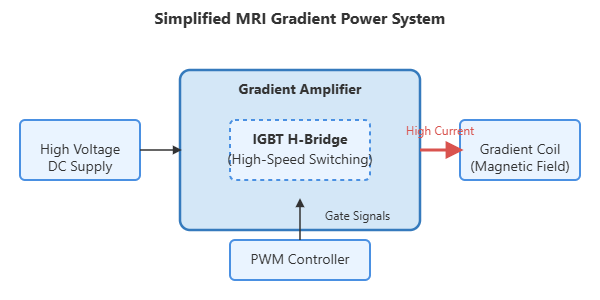
An MRI machine works by using a powerful, static magnetic field to align the protons in the body’s water molecules. To create a 3D image, smaller, rapidly changing magnetic fields—called gradients—are superimposed on the main field. These gradients spatially encode the signal, allowing the system to pinpoint where the resonance signals are coming from. This is where IGBTs are critical.
The gradient amplifiers are essentially massive, high-fidelity audio amplifiers that drive current through the gradient coils. They must produce precise, high-current waveforms (often hundreds of amperes) at frequencies up to several kilohertz. IGBTs, configured in a full-bridge or H-bridge topology, act as the primary switching elements in these amplifiers. They chop a high DC voltage to generate the required pulse-width modulated (PWM) output that, once filtered, creates the desired current waveform in the coils. The IGBT’s ability to switch quickly and handle high currents with low conduction losses is directly linked to the MRI’s performance, influencing factors like image resolution, scan time, and signal-to-noise ratio.
The IGBT’s Function in CT Scanner Gantry Rotation and X-ray Generation
A CT scanner generates cross-sectional images by rotating an X-ray source and detector array around the patient. This requires two major power systems where IGBTs are essential:
- Gantry Motor Drive: The gantry, which can weigh over a ton, must be accelerated, rotated at a constant high speed, and decelerated with extreme smoothness and precision. This motion is controlled by a sophisticated servo drive system. IGBTs form the inverter stage of this drive, converting the mains AC power into a precisely controlled AC waveform to power the gentry motor. Their efficiency minimizes heat generation within the gantry, and their fast switching enables the high-torque, responsive control needed for modern helical scanning techniques.
- High-Voltage Generator for the X-ray Tube: The X-ray tube requires a very stable, high DC voltage (e.g., 120-140 kV) to generate the X-ray beam. This high voltage is produced by a high-frequency inverter, followed by a step-up transformer and rectifier. IGBTs are the switching elements in this inverter. They operate at high frequencies (20-100 kHz) to allow for smaller, lighter magnetic components. Their ability to handle high voltages and provide stable, regulated power is crucial for consistent X-ray dose and quality, which directly impacts image contrast and patient safety.
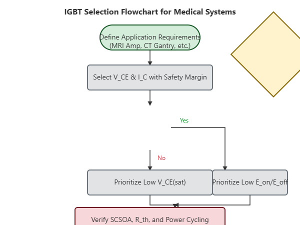
Key Parameter Deep Dive: Selecting the Right IGBT for Medical Applications
Choosing an IGBT for a medical application is far more nuanced than for a standard industrial motor drive. It involves a meticulous trade-off between several competing parameters. A failure to understand these nuances can lead to compromised performance or, worse, premature failure. Engineers should consult resources like our practical guide to decoding IGBT datasheets to navigate these complexities.
Below is a breakdown of the most critical parameters and their specific relevance to medical systems.
| Parameter | Symbol | Importance in Medical Applications | Engineering Consideration |
|---|---|---|---|
| Collector-Emitter Voltage | VCE | Critical for safety and reliability. Must exceed the maximum DC bus voltage with a significant safety margin (typically >50%) to withstand voltage spikes from parasitic inductance. | For 690V AC systems, 1200V IGBTs are standard. For X-ray generators, higher voltage classes like 1700V or even series-connected modules might be necessary. |
| Continuous Collector Current | IC | Defines thermal limit. Must handle the RMS current of the application at the expected operating temperature. In MRI gradient amplifiers, the peak pulse current is also a major consideration. | Select a module where the required RMS current is well within the IC rating at the module’s maximum operating case temperature (e.g., 80°C or 100°C). Models like the Infineon FF450R12KE4 offer robust current handling for demanding applications. |
| Collector-Emitter Saturation Voltage | VCE(sat) | Dictates conduction losses and heat. Lower VCE(sat) means less power dissipated as heat, leading to higher efficiency and simpler thermal management—a key factor in compact, enclosed medical gantries. | Compare datasheets at the nominal operating current and junction temperature (e.g., 125°C or 150°C). A 0.2V difference can result in hundreds of watts of extra heat in a high-power module. |
| Switching Losses (Turn-On/Off Energy) | Eon, Eoff | Dominant loss at high frequencies. Crucial for high-frequency X-ray generators and the PWM in gradient amplifiers. Lower switching losses allow for higher operating frequencies or improved efficiency. | Modern trench-gate and field-stop technologies (e.g., Infineon’s TRENCHSTOP™ IGBT3) offer a better trade-off between VCE(sat) and switching speed. |
| Short-Circuit Safe Operating Area | SCSOA | Defines ruggedness and system protection. The ability to survive a direct short-circuit for a few microseconds until protection circuitry can react. Non-negotiable for expensive medical systems. | Look for a specified short-circuit withstand time (typically 5-10 µs) in the datasheet. This capability is a hallmark of high-quality, reliable IGBT modules designed for mission-critical roles. Explore the concept further at Safe Operating Area (SOA). |
| Thermal Resistance (Junction-to-Case) | Rth(j-c) | Determines heat transfer efficiency. A lower thermal resistance means the heat generated at the silicon chip can be more effectively transferred to the heatsink, keeping the junction temperature lower and improving reliability. | This is a key indicator of the quality of the module’s packaging technology (e.g., advanced baseplates, sintering). A lower Rth(j-c) is always preferable. More on this topic can be found at Wikipedia’s page on Thermal Resistance. |
Application Case Study: Solving Gradient Amplifier Instability in an MRI System
Problem: Image artifacts and system shutdowns due to IGBT overheating and slow switching.
A manufacturer of a new 1.5T MRI system was experiencing intermittent image artifacts, particularly during high-resolution diffusion-weighted imaging (DWI) sequences. These sequences demand the highest performance from the gradient amplifiers, involving rapid, high-current pulses. Field engineers reported that the system would occasionally shut down with a “Gradient Driver Overtemperature” fault. Analysis of the existing gradient amplifier revealed that the installed general-purpose IGBT modules were operating at the edge of their thermal limits. Their switching characteristics were also leading to slight non-linearities in the gradient waveforms under heavy load, causing the subtle image artifacts.
Solution: Migrating to a high-performance IGBT module.
The engineering team decided to replace the incumbent IGBTs with a module optimized for high-frequency, hard-switching applications. The selection criteria focused on lower VCE(sat), reduced switching losses (Eoff in particular), and a lower thermal resistance (Rth(j-c)). A module like the BSM300GA120DN2, known for its balance of performance and reliability, was benchmarked. The goal was to reduce the overall power loss without a complete redesign of the amplifier’s layout or thermal management system.
Result: Enhanced performance and reliability.
The migration to the new IGBT modules yielded immediate and quantifiable improvements.
-
- Thermal Load Reduction: In-system measurements showed a 15% reduction in the total power dissipated by the IGBT modules during the most demanding DWI sequences. The case temperature of the modules dropped by an average of 12°C under peak load.
* Improved Image Quality: The faster and more consistent switching of the new IGBTs resulted in a 20% faster gradient slew rate, leading to sharper images and the complete elimination of the previously observed artifacts.
* Increased Uptime: Over a six-month observation period following the upgrade, there were zero instances of “Gradient Driver Overtemperature” faults across the fleet, dramatically improving the system’s reliability and user confidence.
This case highlights how selecting the right IGBT is not just a component-level decision but a critical factor that directly influences the clinical performance and commercial success of a high-value medical device. Further reading on preventing IGBT failures is essential for robust design.
Practical Design and Integration Tips for Maximum Reliability
Specifying the right IGBT is only half the battle. Proper integration is key to extracting its full performance and ensuring long-term reliability.
Gate Drive Circuit Optimization: The Key to Precision and Protection
The gate driver is the brain that controls the IGBT. In medical applications, it must be robust. Use a driver with a high peak current capability to charge and discharge the IGBT’s input capacitance quickly, minimizing switching losses. Implement a negative gate voltage (e.g., -5V to -15V) during the off-state to provide a strong defense against noise-induced turn-on. Features like Desaturation (DESAT) protection are essential for detecting short-circuits and safely shutting down the IGBT.
Layout and Decoupling: Minimizing Parasitic Inductance
Stray inductance in the DC bus path can cause dangerous voltage overshoots during IGBT turn-off. Keep the layout tight, with wide, flat conductors (laminated bus bars are ideal). Place high-quality, low-ESR film capacitors as close as possible to the IGBT module’s power terminals to provide a low-inductance path for switching currents. Utilizing the module’s Kelvin emitter connection for the gate driver return path is crucial to bypass the effects of source inductance and ensure clean, stable switching.
Thermal Management Strategy: Beyond the Heatsink
A properly sized heatsink is a given, but the thermal interface is just as important. Use a high-quality Thermal Interface Material (TIM) with low thermal resistance and apply it evenly according to the manufacturer’s specifications. Uneven mounting pressure or incorrect TIM application can create hot spots and lead to premature failure. In liquid-cooled systems, ensure proper flow rates and regular maintenance to prevent blockages.
Conclusion: The Future of Power Electronics in Advanced Medical Diagnostics
The IGBT module has firmly established itself as a cornerstone technology in high-power medical equipment. Its unique ability to combine high voltage capability, high current handling, and relatively fast switching speeds makes it the ideal solution for the demanding environments of MRI and CT scanners. As medical technology continues to advance, pushing for higher resolution, faster scan times, and more compact systems, the demands on these power components will only intensify.
Looking ahead, wide-bandgap semiconductors like Silicon Carbide (SiC) are beginning to challenge IGBTs in some areas, offering even higher switching speeds and lower losses. However, for the foreseeable future, the proven reliability, ruggedness, and cost-effectiveness of advanced IGBTs will ensure they remain the dominant power switch in the most demanding medical applications. For engineers and procurement managers in this sector, a deep understanding of IGBT characteristics and a commitment to sourcing high-quality, reliable modules are not just good engineering practice—they are essential for advancing the future of healthcare.
If you are designing or sourcing components for your next medical device project, explore our extensive portfolio of high-reliability IGBT modules or contact our technical team for expert application support.