



Content last revised on September 24, 2026
Radiated-Emissions Evaluation Through Backplate Grounding and Display Cable Control
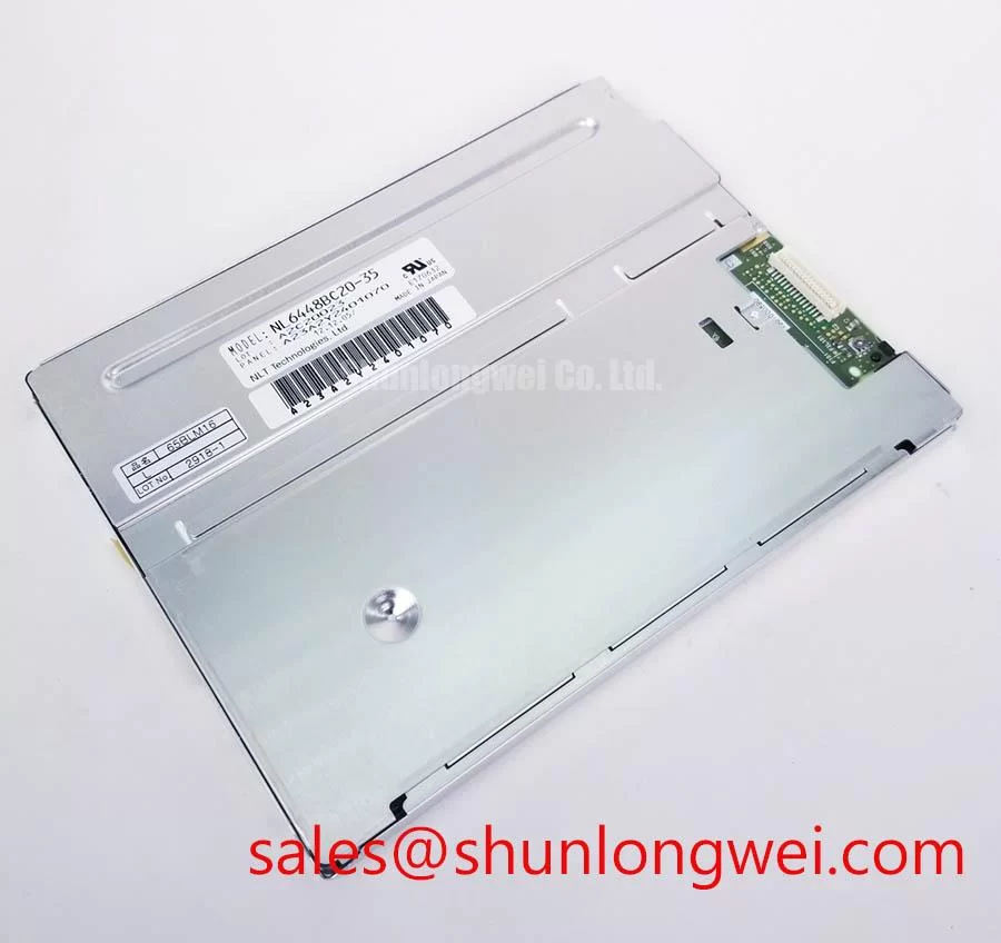
When this panel is evaluated for a petrochemical operator station or field monitoring terminal, the display should be tested inside the same mechanical enclosure used by the host equipment. A bench result obtained with a short temporary cable may not represent the final condition near variable-frequency motor drives, switching supplies, contactors, or long cabinet harnesses. The display cable should follow the intended enclosure route, remain separated from high-current switching conductors where practical, and be supported so that vibration does not transfer repeated stress to the connector.
A suitable Design Consideration is to provide a controlled shield termination at the enclosure entry and to avoid leaving a long unbonded shield pigtail. The exact grounding arrangement remains system-dependent because the panel, cable shield, controller ground, backplate, and protective earth may be connected through different mechanical structures. Engineers should verify common-mode current and display noise during switching tests rather than assuming that a single chassis connection will remove every interference path.
Horizontal noise bands, intermittent pixel disturbance, or unstable image transitions may indicate a cable routing, return-path, grounding, or signal-integrity issue, but these symptoms should not be assigned to one cause without measurement. Compare the display signal at the source and at the panel connector using an appropriate probing method. If the interface uses differential signalling, the system designer should verify the intended differential impedance, pair balance, termination, and skew requirements from the controller and panel documentation. Values such as 100 Ω ± 10% or a particular skew limit must not be treated as confirmed specifications for this model without the applicable interface drawing.
The backplate can provide a useful reference plane when it is mechanically stable and connected according to the enclosure grounding design. This is an Engineering Recommendation, not an NEC factory guarantee. A multi-point connection may reduce high-frequency potential differences in some cabinet layouts, while an unsuitable connection can create circulating current or introduce another return path. The correct arrangement should be verified with conducted and radiated emission measurements on the complete assembly.
For a potential Zone 2 explosion-proof operator station, the display module alone must not be represented as an independent hazardous-area approval or EMC-certified assembly. The enclosure, cable glands, power supply, protective interfaces, temperature limits, and installation method require separate system-level assessment. The panel may be evaluated as one element of a monitoring terminal, subject to the approvals and environmental controls applicable to the finished equipment.
Where a repair team is comparing display architecture or preparing a compatible parts review, the related NL10276BC16-06 can be assessed as a separate same-family display option. Compatibility must be confirmed by connector, timing, mechanical envelope, optical requirements, and host-controller documentation rather than by model naming alone.
Flashlight Dark-Shadow Testing for Logic and Backlight Fault Separation
Begin the optical test in a controlled room with the panel connected to a known-good host system and the image source set to full-screen red, green, blue, white, and black fields. Record the visible condition of the active area before changing cables or applying pressure to the frame. This primary-colour sequence is a practical incoming-QA method for locating fixed pixel defects, line artefacts, uneven illumination, and colour-channel abnormalities without claiming a specific internal failure mechanism.
If the image appears very dark but faint graphics can be seen, place a flashlight obliquely across the viewing surface rather than pressing the lens or glass. A visible image under oblique illumination may suggest that the logic path is producing image data while the illumination path requires further investigation. If no meaningful image structure can be identified, check the host output, cable seating, power sequence, and panel documentation before concluding that the display logic has failed. This flashlight method is a diagnostic aid, not a factory acceptance threshold.
For a suspected line defect, repeat the colour sequence at reduced image complexity and compare the same region across primary colours. A line that remains fixed may require closer inspection of the signal path, connector seating, and panel bonding area. Avoid bending the flexible cable during this test. Mechanical manipulation can create a temporary change that is difficult to reproduce and may worsen the connection condition.
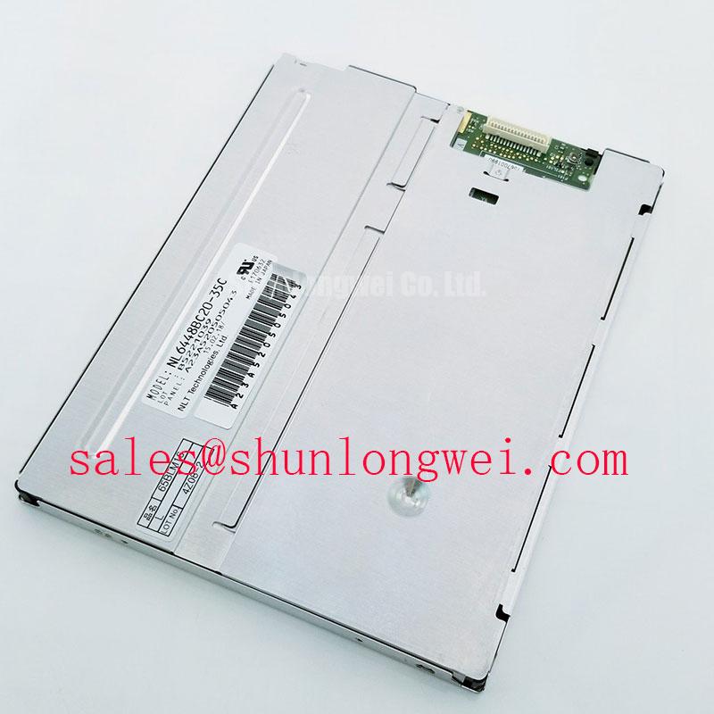
Backlight control must be reviewed from the actual host design. If the system uses PWM dimming, the controller designer should verify the permitted frequency range, duty-cycle behaviour, startup response, and brightness linearity from the relevant backlight documentation. The commonly discussed range of 200 Hz to 1 kHz is a general engineering reference for bench evaluation, not a confirmed specification of the NEC NL6448BC20-35. Audible noise, visible flicker, or brightness steps should be assessed with the complete driver and optical assembly.
Power sequencing deserves the same attention as signal testing. The integrator should confirm enable timing, logic-state behaviour during startup, discharge behaviour after shutdown, and the conditions that could produce a white screen, residual image, or intermittent restart. Do not infer an allowable sequence from a visually successful short test. The original panel documentation and the host controller requirements should define the final sequence.
💡 Bench Tip: Use ESD protection, keep the flexible cable flat and fully aligned during insertion, and close the connector lock without applying sideways force.
For an established service workflow, capture the result of each colour field with the same camera position and exposure settings. This helps maintenance personnel distinguish a repeatable display-area defect from camera artefacts or changing ambient illumination. It also creates a practical comparison record for future service decisions without inventing field-failure rates or lifetime claims.
Polarizer Surface and Viewing-Condition Inspection Under Industrial Lighting
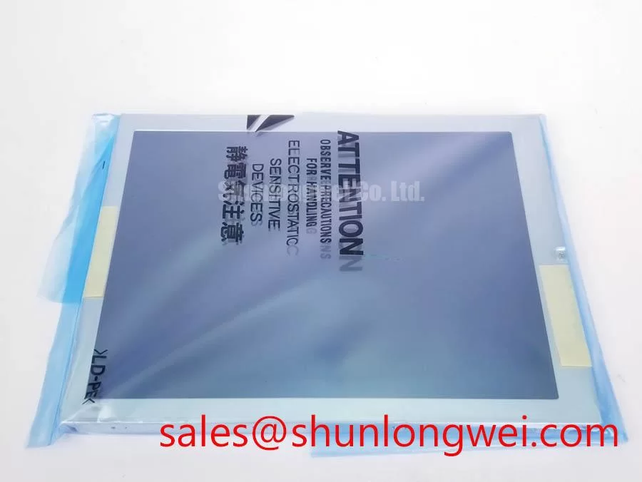
Inspect the front surface with the panel unpowered before introducing bright industrial lighting. A low-angle lamp can reveal scratches, pressure marks, contamination, edge damage, and irregular surface reflections that may be missed when the display is showing a normal user interface. Cleaning should follow the original manufacturer’s handling instructions; the inspection process should not assume a particular polarizer coating, optical retardation film, or adhesive construction unless those details are documented for the exact unit.
Viewing-angle checks should be performed with fixed test graphics containing fine text, grey steps, saturated colours, and dark transitions. Move the observer gradually across the intended operating positions while recording contrast change, grayscale inversion, colour shift, and reflected glare. TN, IPS, and MVA technologies can present different angular behaviours, but the panel technology and viewing-angle figures should be taken from the applicable NEC specification rather than inferred from the appearance of a replacement unit.
In a control cabinet exposed to overhead luminaires or sunlight through a machine-room window, reflected light can reduce practical readability even when the panel image is electrically correct. The enclosure designer should evaluate visor geometry, cover-window reflection, operator position, and ambient illumination together. Anti-glare performance must not be described as a confirmed feature of this model without an authoritative surface specification.
Long-term static HMI screens also require a system-level display policy. Fixed alarm banners, process diagrams, and status bars should be reviewed for their duty cycle and contrast distribution. Periodic screen movement, controlled screen rotation, or reduced static brightness may be considered where the complete display technology and operating conditions make image retention a concern. These are design considerations, not a guaranteed cure or a stated NEC lifetime specification.
Optical bonding should be treated as an enclosure and assembly question rather than assumed from the panel model. If the final operator station requires protection against dust, moisture, cleaning fluid, or condensation, the integrator should verify the cover window, gasket, bonding process, pressure equalisation, and sealing inspection method. The TFT-LCD module itself should not be described as an independently sealed explosion-proof or IP-rated assembly unless the relevant documentation explicitly states that rating.
The related NL10276BC30-24D may be reviewed as a separate display-system component when engineers are mapping a broader panel and backlight architecture. Its presence does not establish electrical or mechanical interchangeability with the NEC NL6448BC20-35. Connector pinout, control method, optical stack, mounting details, and host timing must be checked individually.
Backlight Heat Management and Mechanical Integration
During a brightness test, measure the temperature distribution across the display frame, connector region, rear surface, and nearby enclosure parts after the assembly has reached a stable operating condition. A single surface reading near the centre can miss a local hot region along an edge or around the backlight interface. The thermal result depends on the display, driver, enclosure, airflow, mounting pressure, and ambient conditions, so it should be recorded as a system test rather than presented as a fixed product rating.
An aluminum spreader or chassis rail may be considered when the completed assembly shows a local temperature concentration near the illumination edge. The rail should make stable mechanical contact without loading the glass, squeezing the flexible cable, or obstructing the intended optical area. The exact rail dimensions, interface material, and fastening method must be determined by the enclosure designer after checking the panel drawing and thermal measurements.
Do not assume a particular light-guide material, LED construction, or L70/B50 lifetime value for this model without the applicable factory document. Optical yellowing, brightness drift, and non-uniform illumination can depend on temperature, drive current, duty cycle, ambient exposure, and enclosure heat removal. If long service operation is required, engineers should establish an acceptance test using the actual backlight driver and the intended cabinet conditions.
Mechanical integration also includes flexible-cable bend control. The cable should be routed with a smooth, supported path and should not be trapped between the module and the bezel. Repeated service access should be planned so that technicians can disconnect power before releasing the connector and can reinsert the cable evenly. A display that passes an initial image test can still develop intermittent behaviour if the cable is repeatedly creased, twisted, or pulled through the locking mechanism.
Before approving the panel for a field monitoring terminal, verify the mounting envelope, active viewing area, connector access, backlight drive requirements, signal compatibility, optical readability, and enclosure temperature together. The Industrial Display & HMI Solutions reference can support broader evaluation of display integration in demanding environments, while the final equipment designer remains responsible for validating the complete assembly.