



Content last revised on September 10, 2026
Connector, Display Timing, and Signal Integrity Evaluation
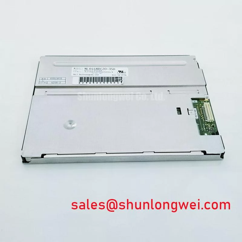
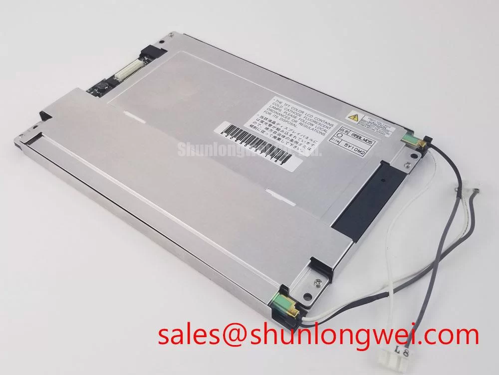
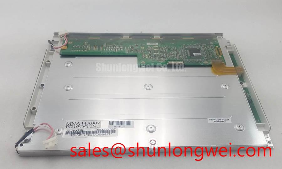
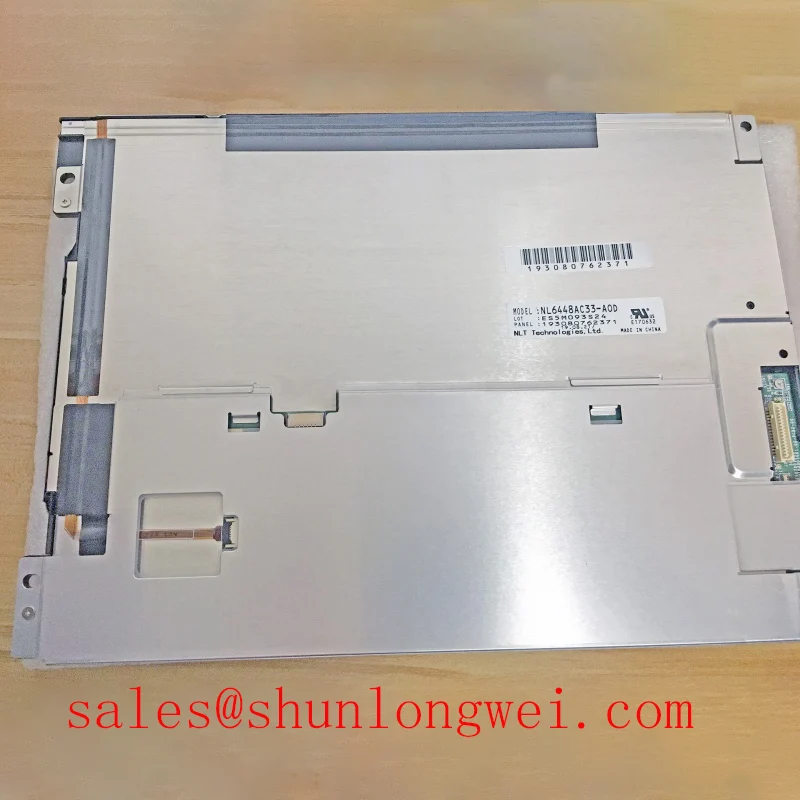
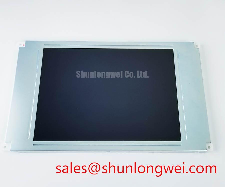
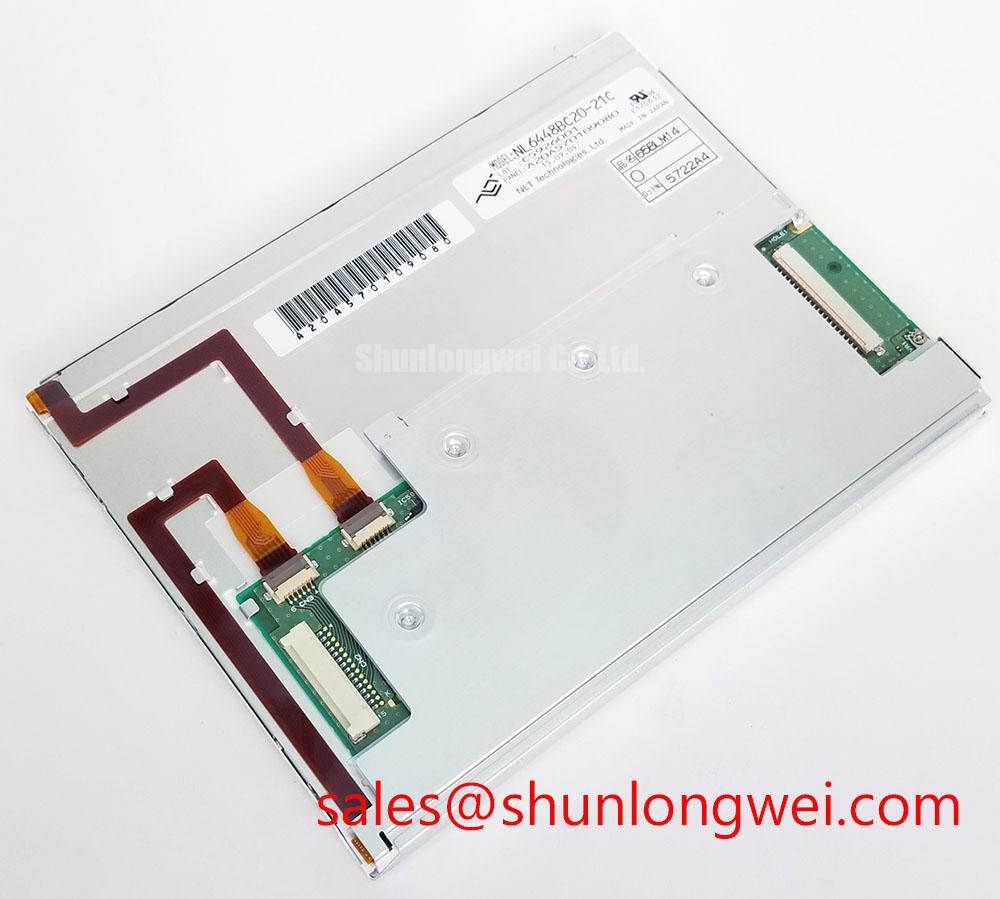
Begin a replacement inspection by comparing the installed panel’s label, connector position, mounting pattern, and cable orientation with the NL6448BC20-21C before applying power. This NEC unit is identified as an Industrial Grade LCD/HMI Panel in a TFT LCD Display Module package.
For overseas repair teams, the primary task is physical and electrical compatibility rather than a visual match alone. Confirm the original equipment documentation, display controller configuration, cable pinout, backlight arrangement, and enclosure aperture before approving a replacement. The product data supplied for this page identifies the manufacturer as NEC and the product category as an industrial LCD/HMI panel; system-specific interface and power details should be checked against the original panel documentation.
A replacement display should be evaluated from the connector outward. Count the pins on the installed cable, identify the keyed orientation, and compare the cable drawing with the panel documentation. A similar connector shell does not prove electrical compatibility. The system integrator should verify whether the host uses LVDS, TTL, or another display signaling arrangement, together with the required logic supply voltage and power sequencing.
When the host uses differential LVDS, the receiver depends on controlled routing from the display controller to the panel connector. The signal path should maintain a consistent differential geometry, avoid unnecessary stubs, and keep paired conductors routed together through bends and transitions. A nominal 100 ohm differential characteristic impedance is a common high-speed interconnect design consideration, but the final routing requirement belongs to the host board, cable, connector, and panel interface combination. The system engineer should validate the actual channel with the approved panel pinout and signal integrity measurements.
Pixel clock quality is often assessed first when a display shows intermittent vertical bands, split images, unstable text, or a picture that changes after cable movement. These symptoms can have several possible causes, including data mapping errors, cable termination problems, connector contact variation, grounding differences, or timing configuration mismatch. A known-good signal path and oscilloscope comparison are more useful than assigning the fault to the panel without measurement.
JEIDA and VESA data mapping must also be aligned with the transmitter configuration. Incorrect mapping can produce incorrect color levels, abnormal grayscale transitions, or a stable image with wrong color relationships. The replacement evaluation should therefore include a check of bit ordering, color channel assignment, synchronization signals, and pixel clock polarity where applicable. These are integration conditions, not independent factory guarantees for the NL6448BC20-21C unless confirmed by the original NEC documentation.
Power-on behavior deserves the same attention as the signal wiring. The controller should not be connected to an unverified panel simply because the connector fits. Designers should verify the required supply voltage, enable order, reset behavior, and allowable rise and fall characteristics from the original panel documentation. If the host applies power before the display control signals are valid, the resulting behavior may include a blank screen, unstable initialization, or repeated start attempts.
Backlight control should be tested independently from image data. Where the host provides PWM dimming, verify that the controller’s frequency, polarity, duty-cycle response, and enable timing are accepted by the actual backlight circuit. The stated frequency range in a system design brief should not be treated as an NL6448BC20-21C factory rating unless it appears in the applicable NEC specification. Check brightness response at low and high command levels, then inspect the image for visible flicker during static text and telemetry screens.
💡 Pro Tip: Keep each high-speed differential pair routed as a matched path through the controller and cable interface, then confirm clock and data timing against a known-good display before changing firmware settings.
Suppressing Localized Thermal Gradients During Long Display Operation
Thermal inspection should begin with the complete display assembly rather than the LCD surface alone. In a retrofit enclosure, heat can enter through the controller board, backlight driver, nearby power conversion components, or an unventilated rear cover. A display that appears correct during a short bench test may show brightness nonuniformity or color drift after the enclosure reaches its operating temperature.
Use an infrared inspection method or contact temperature measurement to compare the display perimeter, rear frame, cable region, and adjacent electronics under representative brightness and image conditions. The purpose is to locate temperature gradients, not to infer a hidden internal construction. Any heat-spreading rail, bracket, or rear support added by the system designer should avoid pressure on the glass, interference with the flex cable, and distortion of the mounting frame.
Mechanical heat spreading is a design consideration for installations where the display is close to hot electronics. The rail or bracket should be sized from measured heat paths and available enclosure space, with the final thermal result verified during the system qualification test. Avoid treating an aluminum support as a guaranteed cooling solution: its effect depends on contact quality, airflow, enclosure materials, and the heat generated by the complete assembly.
Long-term optical changes can also be affected by uneven heating, excessive brightness settings, contamination on the front surface, and repeated thermal cycling. Without an authoritative reliability report for the exact panel revision and operating profile, a specific optical lifetime or color-shift prediction should not be assigned to this model. Record brightness uniformity, white balance, and representative image appearance at the beginning of the evaluation so later maintenance checks have a consistent reference.
Signal integrity and thermal behavior should be checked together when the panel is installed in a heavy mining shovel or earthmoving equipment telematics display. Vibration can alter connector contact pressure or cable routing, while enclosure temperature can change the electrical behavior of the host electronics. The application is therefore a compatibility example, not a claim that the NL6448BC20-21C is certified for a particular vehicle, machine, or environmental duty.
For a same-size or same-resolution replacement study, engineers may place NL10276BC16-06 beside the NEC unit for a neutral interface comparison. Mechanical dimensions, active area, connector placement, optical characteristics, and controller timing still require individual confirmation; similar product naming does not establish drop-in interchangeability.
Wide-Angle Image Evaluation for Multi-Position Operator Consoles
Viewing-angle evaluation should be performed from the actual operator positions rather than from a single centered seat. Check small text, warning icons, grayscale ramps, and dark backgrounds while viewing from above, below, and both sides. This reveals whether the installed panel maintains readable contrast and stable color when the machine operator is not directly in front of the display.
Panel technology, optical film selection, surface treatment, and host calibration all influence the result. A panel described in general terms as wide viewing angle should not automatically be assigned a specific symmetric viewing figure without the relevant factory data. The values 85°/85°/85°/85° should only be used when confirmed by the applicable NEC datasheet for this exact suffix and revision. Otherwise, measure the practical viewing envelope required by the console and compare it with the original unit.
TN, IPS, and MVA panels can present different grayscale behavior at oblique angles. A replacement may preserve the image geometry while changing perceived black level, mid-tone contrast, or color balance. This matters in telematics displays where operators read map colors, hydraulic status bars, camera overlays, and alarm text under changing cabin light. The controller’s gamma configuration should be checked before attempting to correct an apparent optical mismatch through software.
The T-CON and host display engine should be evaluated as a matched pair. Gray-level voltage generation, gamma correction, frame timing, and source-driver control affect whether gradients appear smooth or show visible steps. If the replacement produces uneven grayscale, compare the panel initialization sequence and gamma settings with the known-good configuration. Do not assume that a firmware table from another NEC display is suitable for the NL6448BC20-21C.
Surface glare is another field variable. A glossy or semi-gloss surface can improve perceived contrast in controlled lighting but may reflect cabin windows, work lights, or instrument illumination. An anti-glare surface can reduce reflections while changing fine-text readability and apparent sharpness. Assess the front surface with the equipment’s normal lighting arrangement, and confirm that the enclosure bezel does not create a shadow or reflective edge around the active image.
Clock jitter and data hold behavior should be considered across the expected operating temperature range of the complete system. If the screen becomes unstable only after warm-up or during vibration, inspect the host clock source, cable shielding, connector retention, grounding path, and supply stability before replacing the panel again. These observations guide engineering verification; they do not establish a single component-level failure cause.
The Industrial Display and HMI Solutions reference can be used when defining broader enclosure, interface, and environmental test plans. It should supplement, not replace, the exact NEC documentation for connector definition, optical performance, and electrical limits.
Thermal Cycling, Polarizer Bonding and Perimeter Gasket Inspection
Before installation, inspect the glass edge, bezel, flex-cable exit, connector reinforcement, and perimeter sealing surfaces under clean lighting. Look for lifted trim, contamination, mechanical distortion, or marks that could become pressure points after the module is clamped into the equipment housing. The inspection should be documented with photographs and compared with the enclosure drawing.
Low-temperature operation can change liquid-crystal response behavior and may increase visible transition lag during the first minutes after startup. This is a system-level evaluation point rather than a basis for assigning a guaranteed gray-to-gray response under every thermal condition. Test the actual screen content used by the machine, including rapidly changing numeric fields, moving trend lines, and alarm transitions. Compare startup response, stabilized response, and recovery after temperature exposure.
At elevated temperature, inspect brightness stability, uniformity, image retention, and the backlight control response. At lower temperature, verify that the host does not interpret a delayed image transition as a communication fault. The complete qualification plan should define dwell conditions, ramp behavior, powered and unpowered states, and post-test inspection criteria according to the equipment requirements and applicable environmental standards.
Adhesive and sealant behavior cannot be predicted reliably from the model number alone. The original enclosure should preserve the manufacturer’s intended support points without concentrating force on the active area. If a gasket is replaced, select a material and compression method based on the enclosure’s sealing and service requirements, then verify that the bezel does not bow or transfer load into the glass.
Backlight PWM should be assessed after thermal cycling because control behavior can change with the driver, wiring, and host firmware. Designers should verify enable timing, brightness repeatability, and visible flicker using the actual controller and cable assembly. If audible noise appears, examine the complete backlight driver and mechanical enclosure rather than attributing it to the LCD panel without evidence.
When the NL6448BC20-21C is considered for a replacement in a heavy mining shovel or earthmoving equipment telematics console, the final review should cover connector compatibility, mounting alignment, front aperture clearance, cable bend path, image calibration, backlight control, and thermal response. The documented NEC identity and TFT LCD module category support product-level sourcing work, while electrical limits and environmental acceptance remain subject to the original factory documentation and the equipment designer’s validation plan.