

Content last revised on October 27, 2026
Preventing Spurious Faults: AC Input Transient Overvoltage Clamping Guidelines for MDS3001664
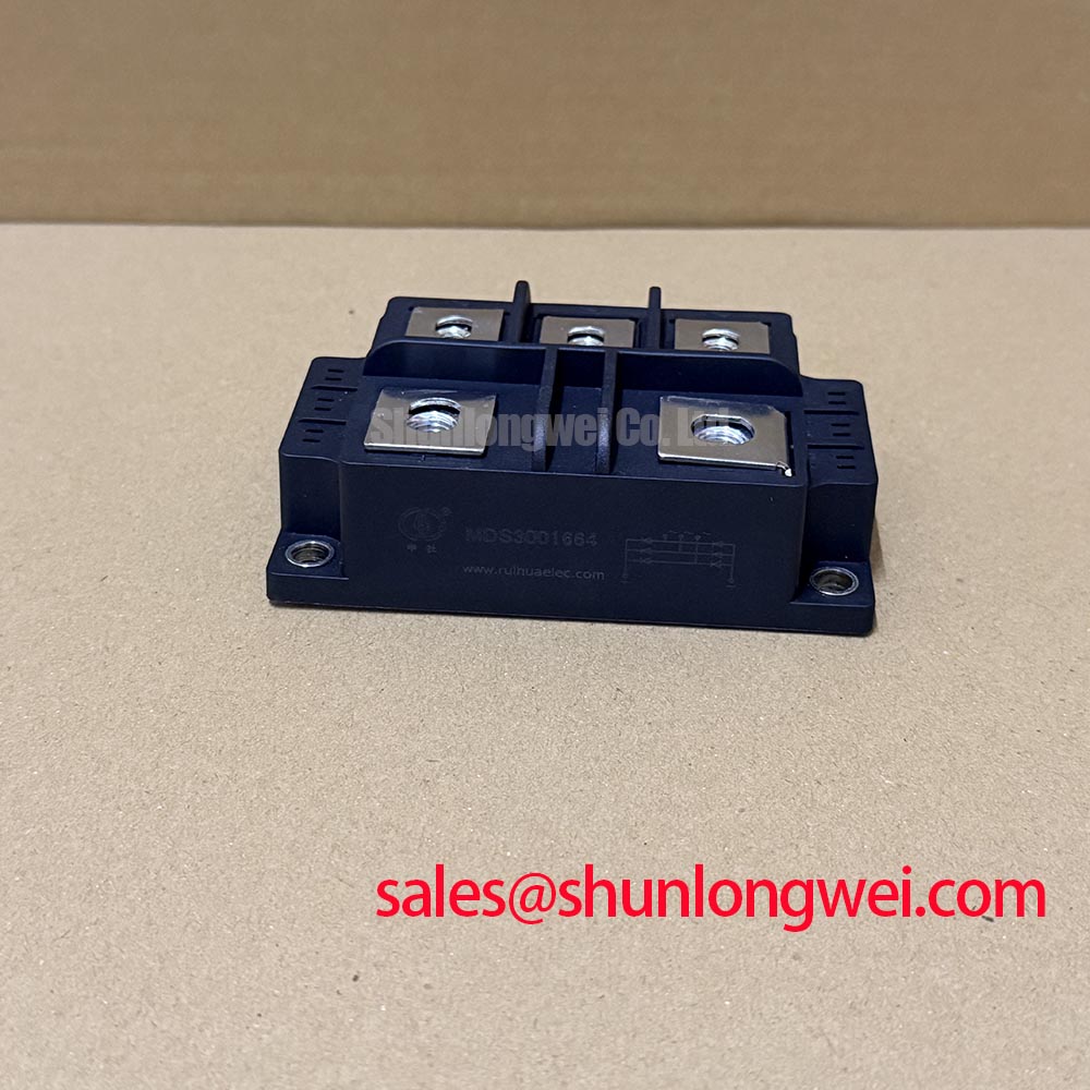
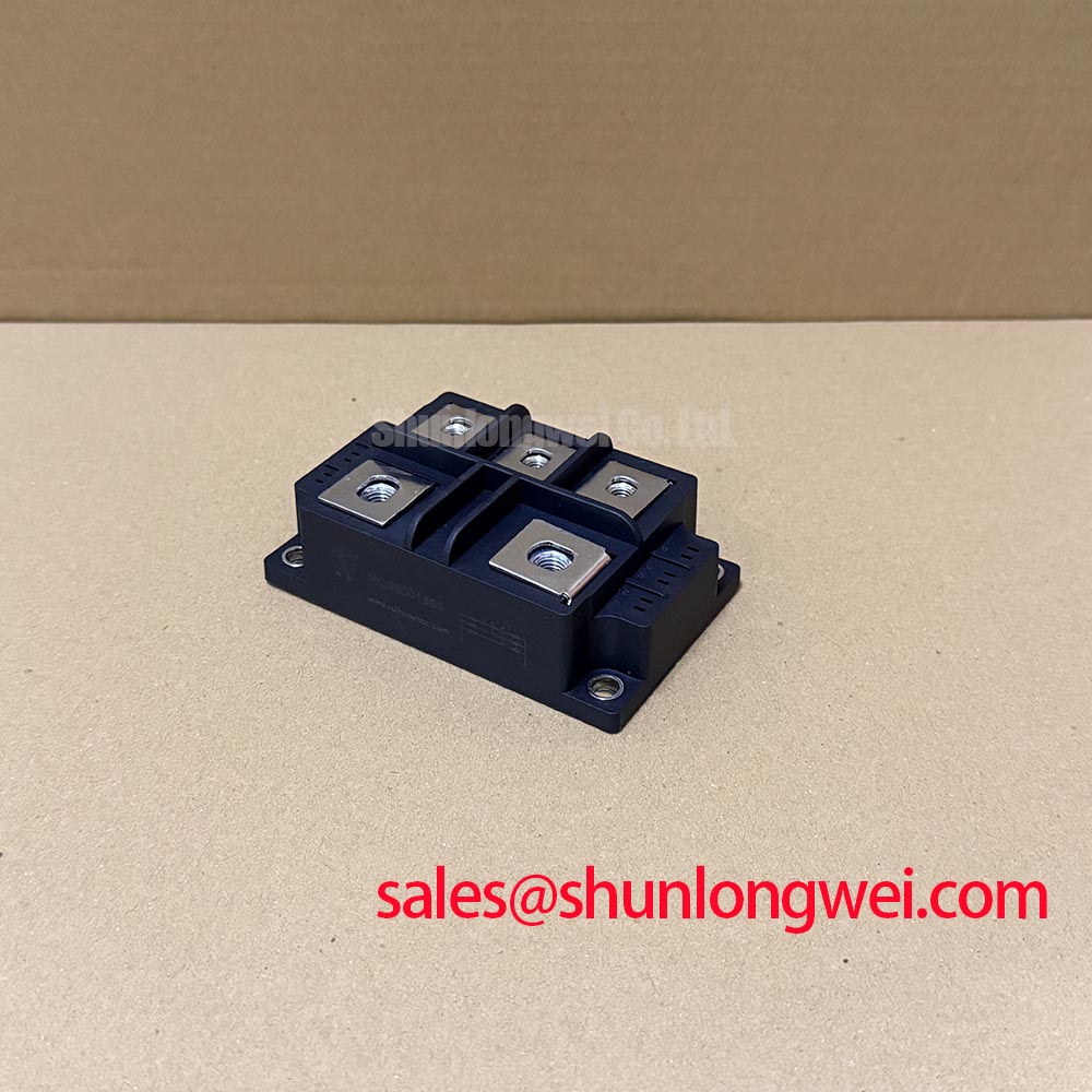
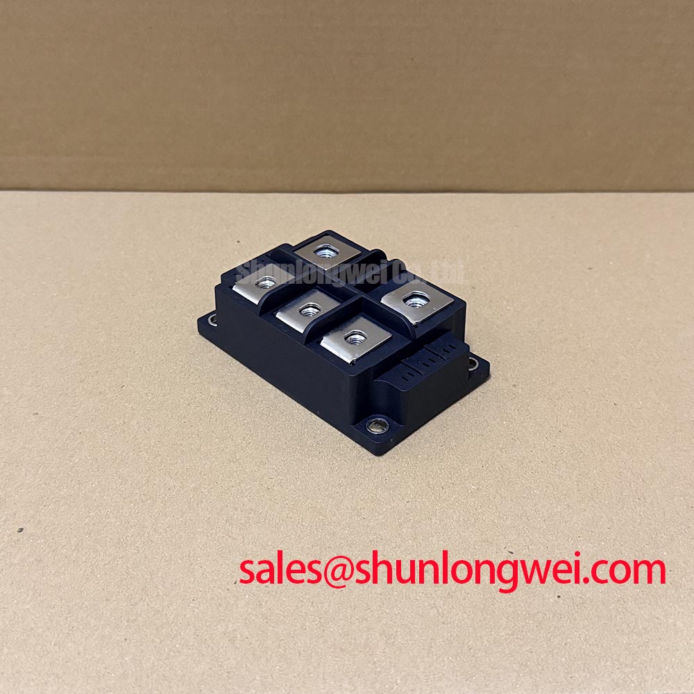
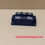
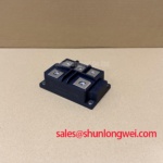
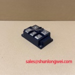
When a high-current DC rectifier trips during electrolyzer operation, isolate the AC source, discharge the DC link, and check the bridge terminals for abnormal cold-state impedance, loose hardware, and visible case damage before applying another test pulse. The device identified here is the SanRex, also associated with Sansha Electric, MDS3001664 three-phase rectifier module. Confirm the exact part marking, voltage and current ratings, and package configuration against the manufacturer’s documentation before selecting, testing, or replacing the module.
For a high-current green hydrogen electrolyzer DC power rectifier, the catalog identity is not a complete system operating prescription. The rectifier assembly, transformer arrangement, semiconductor protection, cooling path, and control strategy must be evaluated together. When comparing a replacement or parallel architecture, engineers may also review the linked MDS500-12 as a separate reference model, without treating it as an automatic substitute.
Transient protection should be coordinated from the incoming three-phase network toward the rectifier terminals, with the fuse, surge suppressor, switching device, and commutation loop considered as one protection path. A metal oxide varistor selection is a design consideration: its continuous operating voltage, surge energy capability, clamping behavior, and short-circuit coordination must match the actual line arrangement and transformer impedance. The MOV should not be selected from the module’s voltage rating alone.
For installations evaluated against IEC 61000-4-5 surge conditions, place the surge-current path so that lead inductance does not force the transient around the intended clamp. An RC snubber can be considered across the relevant switching or rectifier junction path when ringing is confirmed during testing. Its resistance, capacitance, pulse energy, and damping response are system-dependent; the final network should be validated with differential voltage probing during controlled switching tests.
Fuse coordination must use the manufacturer’s applicable I²t data and the fuse’s clearing characteristics, not only its continuous current label. The protection review should compare the prospective fault current, fuse let-through energy, semiconductor surge capability, and the wiring impedance between the protective device and the module. Confirm that each AC phase is connected to the correct power terminal and that the enclosure wiring cannot transfer mechanical force into the case terminals.
Terminal preparation is especially important in a high-current assembly. Clean mating surfaces, use the specified hardware sequence, and apply the terminal tightening torque stated for the actual mechanical interface. The product information supplied for this page does not define a module-specific torque value, so the installation drawing and approved assembly procedure control that setting. ⚠️ Field Alert: Never reconnect or retighten power terminals while the DC link or auxiliary control circuits remain energized.
MDS3001664 Thermal-Electrical Optimization: High-Reliability Multi-Bridge Architecture Practical Tuning
Parallel bridge arrangements require deliberate current sharing, especially when the rectifier feeds a kiloampere-level DC bus for an electrolyzer stack. A six-pulse bridge uses one three-phase secondary arrangement, while a twelve-pulse system combines phase-shifted bridge outputs. Parallel-connected twelve-pulse arrangements may use an interphase transformer or equivalent current-sharing network; series-connected arrangements do not require the same parallel current-sharing scheme. The correct topology depends on transformer phasing, DC ripple targets, circulating-current control, and the electrical limits of the complete power stage.
Where an interphase transformer is used, it should be checked for correct polarity, saturation behavior, insulation coordination, and thermal loading under the actual waveform. Verify the required phase displacement at the rectifier transformer secondaries. Unequal current between parallel bridge paths can arise from wiring resistance, transformer mismatch, unequal thermal contact, or terminal pressure variation. During commissioning, compare branch currents under the same operating condition and inspect the current-sharing network before changing control parameters.
For a pressure-contact or double-sided cooling arrangement, the mechanical stack is part of the electrical design. Parallel faces should remain clean and flat, with the approved pressure hardware distributing force evenly across the contact area. A Belleville washer or disc-spring stack may be used where the equipment design specifies one, but its calibration belongs to the assembly procedure rather than a universal value for this module.
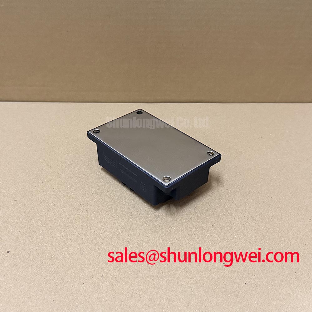
Where a baseplate and heatsink are used, apply the selected thermal interface material as a continuous, uniform film without trapping air or contaminating the terminal surfaces. The correct layer condition depends on the mating flatness, compound specification, clamping method, and thermal test results. Designers should verify case temperature, heatsink temperature, airflow or coolant performance, and phase-current balance at the intended electrolyzer load.
DC-link ripple also affects the surrounding capacitor bank and busbar system. Film capacitors are commonly evaluated in high-ripple DC-link applications; the film capacitor reference provides general background, while the actual capacitor ripple-current rating and lifetime assessment must come from its manufacturer. Keep the high-current commutation loop compact and validate voltage sharing at the bridge terminals.
MDS3001664 Circuit Protection & Reliability: Evaluating Post-Surge Reverse Voltage Block
After a surge event, do not judge the bridge only by whether the DC output returns. First remove stored energy, isolate every phase, and inspect the terminal block, protective devices, busbar insulation, and cooling contact. A post-surge reverse-voltage check should be performed with the module disconnected from parallel paths, because transformers, snubbers, MOVs, and capacitor banks can create misleading measurement paths.
The sinusoidal 10 ms half-cycle surge rating, when specified in the applicable factory documentation, is the reference for evaluating an overcurrent event. It should be compared with the fuse clearing profile and the actual fault waveform. A fuse that clears successfully may still leave thermal or mechanical stress in the rectifier assembly, so the inspection should include terminal discoloration, pressure-stack movement where applicable, heatsink contact, and abnormal leakage behavior under an approved test method.
Before reverse voltage is reapplied, establish the junction-temperature condition from the cooling system and recent load history. Junction temperature is influenced by forward conduction loss, current sharing, thermal interface quality, heatsink performance, and ambient conditions. The manufacturer’s specified reverse-voltage rating should be assessed against the real reverse-voltage waveform, including transformer transients and commutation overshoot, rather than treated as a standalone immunity claim.
Reliability decisions should also account for enclosure materials, contamination control, and thermal cycling. PEEK is widely discussed for durable polymer applications in demanding environments; the PEEK materials reference is useful background, but it does not establish the material construction of this SanRex module. For broader switching-device design context, engineers can consult the Wide Bandgap Revolution technical guide.
Before returning the rectifier to service, record the phase connections, fuse condition, surge-protection status, terminal torque verification, cooling-interface condition, and measured voltage balance. That record gives the next maintenance team a practical baseline for distinguishing a protection event from a thermal-contact or current-sharing problem.