

Content last revised on September 20, 2026
Transient Dynamics & Electrical Design: AC Line Surge Immunity and Lightning Transients on MDS400-16
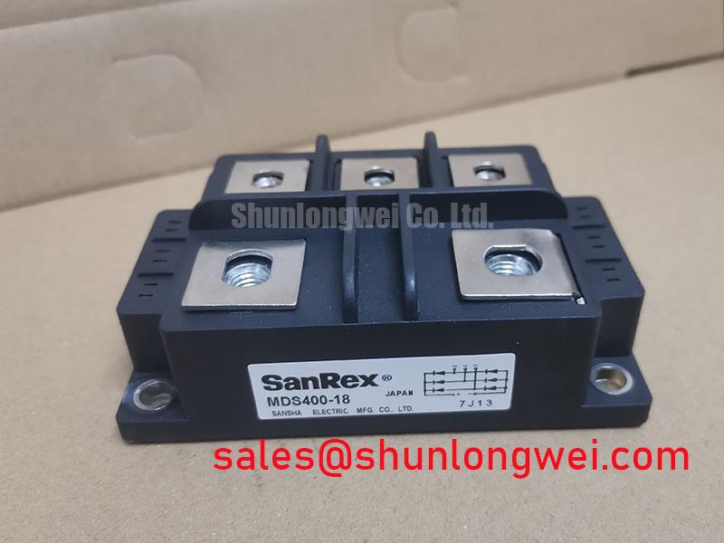
The 1600 V VRRM rating is a repetitive reverse-voltage specification, not a blanket declaration of immunity to lightning or utility switching events. For a furnace input stage, the designer should map the upstream transformer impedance, line configuration, commutation behavior and protective-device let-through characteristics before accepting the module as a direct replacement.
A surge protection study may refer to the test concepts in IEC 61000-4-5, but the finished rectifier assembly must be evaluated as a system. MOV selection, line fusing and any RC suppression network should be coordinated with the actual AC source and enclosure wiring. The supplied product data does not define a universal MOV voltage, RC value or fuse I2t coordination point, so those values must be taken from the equipment protection study and the applicable module documentation.
The 5500 A half-sine surge rating describes the module’s specified forward surge capability under its stated test conditions. It should not be interpreted as permission to expose the device repeatedly to uncontrolled short circuits. A semiconductor fuse and the rectifier’s fault-clearing path should be checked together, including prospective fault current, clearing time and the fuse I2t value. For a system-level comparison, engineers may also review the neutral reference unit SKD 25/14, while retaining the original circuit’s voltage and current requirements as the governing criteria.
Assembly Integrity & Layout Architecture: Implementing AC-to-DC Transfer Characteristics Across V
In a furnace power converter, the bridge output and any controlled downstream stage are affected by transformer condition and load behavior. The MDS400-16 provides the high-current rectifier stage; it does not establish the control algorithm, firing-angle range or power-factor performance of the complete system. Designers should verify the terminal identification and phase sequence from the original equipment schematic before energizing a replacement.
At low firing angles, the supply may draw substantial real power while the commutation path and transformer leakage still influence the waveform. At larger firing angles, average DC output generally falls while reactive current and waveform distortion can become more important to the upstream supply. These are system characteristics that require oscilloscope and power-analyzer verification rather than assumptions based only on the module’s current rating.
Layout should keep the AC input path, rectified output path and protection loop physically controlled to reduce unwanted stray inductance. The electrically insulated base simplifies isolation planning, but the complete assembly still requires appropriate creepage, clearance, barriers and cable routing for the working voltage. The stated 2500 V AC for 1 minute isolation rating belongs to the specified module test condition and does not independently certify the furnace cabinet or the finished power converter.
When the rectifier is used with a larger supply or trigger topology, the related SKD82/18 page can be reviewed as a neutral reference for a different system position. It should not be treated as an automatic substitute or proof of electrical interchangeability.
MDS400-16 Circuit Protection & Reliability: Calibrating Baseplate Thermal Resistance
The published 0.065 °C/W junction-to-case thermal resistance per element is useful only when the case interface is assembled correctly and the heatsink temperature is known. During evaluation, inspect the mounting face for contamination, burrs, distortion and uneven contact. Apply the thermal interface material according to the equipment manufacturer’s process, then verify that the fastening method produces even contact without bending the module body.
The insulated mounting base should be incorporated into the mechanical insulation review rather than assumed to solve every cabinet-level dielectric requirement. Check the heatsink surface, insulating hardware, protective earth arrangement and test method used by the equipment manufacturer. A production insulation test must be defined for the complete assembly; the module’s 2500 V AC one-minute rating is not an independent EMC or safety certification for the furnace.
Thermal validation should use measured case temperature, estimated power dissipation and the specified junction-to-case value. The operating junction range is −40 °C to +150 °C, but the system engineer must calculate the actual junction condition under continuous load, overload recovery and ambient temperature variation. No field-life or failure-rate conclusion should be drawn from the rating alone.
💡 Pro Tip: De-energize and verify the DC bus has discharged before removing any rectifier connection, then recheck terminal torque and insulation clearances during reassembly.
For package material and thermal-interface background, engineers can consult the general references on Polyphenylene Sulfide and eutectic gold-tin solder systems; these references do not establish undocumented internal construction details for this specific module.
MDS400-16 Operational Boundaries: Evaluating Commutation Turn-Off Voltage Limits
The available product parameters identify the reverse-voltage limit, forward-current rating, surge-current rating, thermal resistance, isolation voltage and junction-temperature range. They do not provide a confirmed reverse-recovery peak current, reverse-recovery time or softness factor for this specific unit. Those values should not be inferred from the 1600 V rating.
In a medium-frequency induction furnace supply, commutation behavior is affected by transformer leakage, line inductance, load current, firing control and the protection network. During commissioning, measure the voltage across the rectifier terminals and inspect the current waveform during the most demanding operating transition. The measured peak should be compared with the repetitive voltage rating and the transient protection design, while the junction temperature should be checked under the same operating condition.
Minimize the commutation loop area where practical to reduce parasitic voltage overshoot, then verify the result with a properly rated differential probe and current measurement method. If the waveform indicates excessive ringing or abnormal recovery behavior, review snubber placement, transformer leakage, fuse coordination and trigger timing as a combined network rather than assigning the symptom to one component without measurement.
For practical commutation and power-layout principles, the Precision Gate Drive Design reference provides additional system-level context. Any protective clamp, snubber or active control setting remains a design decision that must be validated on the completed power assembly.