

Content last revised on September 20, 2026
MEO500-06DA Service Inspection and Application Context
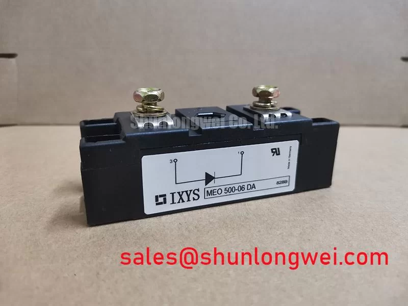
With power isolated, begin service inspection by checking the MEO500-06DA terminals for loose hardware, heat-discolored conductors, cracked insulation, and unexpected low-resistance paths between the external power connections and the mounting surface. The MEO500-06DA from IXYS is a dual diode module rated at 600 V and 514 A in the SOT-227B / TO-240AA package. These are Official Datasheet Specifications and establish the electrical and mechanical identity that must be matched before a repair decision is made.
For a high-voltage three-phase motor solid-state soft starter, this diode module should be assessed within the actual rectifier, freewheel, bypass, or DC-link support arrangement used by the equipment. A dual diode module has no gate terminal or firing-angle control function of its own. Gate pulse timing, firing delay, and holding-current behavior belong to the controller and the associated thyristor devices. Keeping that boundary clear prevents an incorrect diagnosis when a soft starter has failed to ramp, commutate, or transfer to its bypass contactor.
| Parameter | Value | Status |
|---|---|---|
| Manufacturer | IXYS | Product identification |
| Product model | MEO500-06DA | Product identification |
| Module type | Dual diode module | Product classification |
| Rated voltage | 600 V | Official Datasheet Specification |
| Rated current | 514 A | Official Datasheet Specification |
| Package | SOT-227B / TO-240AA | Official Datasheet Specification |
Transient Dynamics & Electrical Design: Semiconductor Protection Fuse Selection for MEO500-06DA
In a stalled-motor or DC-bus short-circuit investigation, first record the fuse part number, its time-current curve, its pre-arcing and total-clearing I²t data, and the exact location of the fuse relative to the MEO500-06DA. The module’s 600 V rated voltage does not by itself confirm suitability of a replacement fuse. The system engineer must coordinate the selected semiconductor fuse with the prospective fault current, source impedance, conductor arrangement, and the complete power-device protection limits documented for the original equipment.
Fuse I²t coordination is a Design Consideration rather than an official module parameter where no module-specific surge-energy value has been supplied. A fuse that clears too slowly can expose the diode junctions and busbar structure to damaging fault energy. A fuse that is poorly matched to normal starting duty can create nuisance interruptions during a legitimate motor acceleration cycle. Review the original protection table where available, then compare its stated clearing behavior against the installed starter’s measured or documented fault conditions.
Terminal connections deserve the same attention as the fuse. Check that power lugs sit flat, that no cable strand is trapped beneath a lug, and that the contact surfaces are clean before reassembly. The module mounting hardware and terminal hardware must follow the equipment documentation and the applicable fastener specification; no mounting-torque value is stated here as an Official Datasheet Specification.
⚠️ Field Alert: Disconnect and verify the stored-energy path is safe before removing power cables, then tighten terminals and mounting hardware only to the original equipment’s specified torque.
Transient voltage also depends on loop inductance and interruption speed. Where an oscilloscope review shows recurring switching overshoot, inspect the existing suppression network, wiring route, and DC-link layout rather than assigning the problem to the diode module alone. The operating principle of an RC or related clamp network is described in this reference on snubber circuit networks. Any change to a suppression circuit requires system-level switching tests to verify peak voltage against the 600 V module rating and the complete circuit margin.
MEO500-06DA Thermal-Electrical Optimization: Dynamic Firing Delay Angle Adjustment Under Practical Tuning
During a soft-starter commissioning check, observe the commanded firing pattern and the actual line current together. A phase-angle controller changes the conduction interval of its controlled semiconductor devices as firing delay changes. This alters motor terminal voltage, acceleration torque, input current waveform, power factor, and reactive-power demand. The MEO500-06DA can participate in the power path as a dual diode module, but it does not generate or interpret firing commands.
When the controller moves through a firing-delay range, uneven current between phases may point to several conditions: a missing synchronization reference, a weakened firing-pulse path, an open control connection, an abnormal load, an upstream supply imbalance, or a power-device issue. Treat these as testable possibilities. Compare all phase waveforms against a known-good channel or against the equipment manufacturer’s expected waveform. Do not adjust phase-angle settings based only on a clamp-meter reading during a rapidly changing acceleration sequence.
The 514 A current rating is an Official Datasheet Specification, not a statement of permitted motor starting current, overload duration, or soft-starter output capacity. Those limits are determined by the starter topology, thermal design, ambient conditions, protection coordination, and the original drive documentation. For practical repair work, verify whether the failed unit’s current path includes the diode module continuously or only during selected commutation and bypass states.
If a replacement evaluation is required, match the device function, polarity arrangement, package interface, electrical ratings, insulation arrangement, terminal layout, and thermal mounting conditions of the original assembly. A linked SKN320-04 listing can be consulted as a related power-semiconductor reference, but it is not an automatic substitute for the MEO500-06DA. Compatibility must be established from the equipment schematic and the relevant manufacturer documentation before installation.
Where heat-related symptoms appear only after repeated starts, inspect the heatsink interface, airflow route, contamination, fan operation, and clamping condition. Thermal cycling can affect module interfaces and assembly hardware over time; the general test concept is covered by thermal shock testing under MIL-STD-202 context. It does not provide a field-life prediction for this module or this equipment.
MEO500-06DA Thermal-Electrical Optimization: Thermal Duty Cycle Management of Bypass Control
A bypass contactor normally changes the thermal burden inside a phase-angle soft starter after the motor reaches the intended operating condition. Before attributing repeated overheating to the MEO500-06DA, confirm whether the bypass contactor closes when commanded, whether its auxiliary feedback reaches the controller, and whether the power path actually transfers. A contactor that fails to close can leave the controlled semiconductor path conducting longer than intended. A contactor that closes incorrectly can create a different fault condition. Both require measurement and circuit tracing.
Motor locked-rotor current is often substantially higher than normal running current, but its actual value and duration must come from the motor data, driven-load condition, and starter settings. The objective of phase-angle starting is to control acceleration current and reduce mechanical shock, while retaining enough torque for the connected load. Designers and service engineers should verify that the current limit, ramp behavior, thermal model, and bypass sequence correspond to the original equipment configuration.
For the MEO500-06DA, use the 600 V and 514 A Official Datasheet Specifications as fixed identity checks, then separately validate the module’s placement in the starter. Check each diode path with an appropriate meter method while the module is isolated from parallel circuit paths where practical. A reading influenced by snubbers, capacitors, transformers, or adjacent semiconductors does not establish a module fault. Compare directional behavior between the two internal diode paths and investigate deviations through the actual schematic.
Apply thermal compound as required by the original assembly instructions, maintain even heatsink contact, and avoid mechanical stress from rigid busbars pulling the module out of plane. These are Design Considerations for reliable power-module assembly, not factory guarantees for the MEO500-06DA. Engineers examining duty-cycle stress and industrial power-stage service practices can also use this Industrial Applications reference as a broader troubleshooting resource.
Preventing Spurious Faults: High-di/dt Gate Firing and Pulse-Train Timing Around MEO500-06DA
When a solid-state soft starter shows intermittent phase loss, poor acceleration, or unexplained protective trips, separate diode-module checks from thyristor gate-drive checks. The MEO500-06DA has no gate connection. Pulse rise time, pulse-train duration, back-porch behavior, gate current, and firing synchronization must be measured at the control terminals of the associated thyristor assembly, using the original circuit reference and safe isolated measurement practice.
A multi-pulse firing arrangement can help a controller maintain reliable triggering across changing load and supply conditions, but the correct pulse pattern is system-determined. Inspect the pulse transformer or isolated driver connections, gate-return route, synchronization input, and controller supply stability. A distorted pulse may indicate a control-side problem, while a healthy pulse combined with abnormal power current may direct attention toward the power semiconductor path, connections, protection network, or load.
High current change rates can magnify the effect of stray inductance in busbars and cable connections. Minimize unnecessary loop area where the equipment construction permits, particularly around the relevant switching and suppression path, then verify electrical behavior during controlled tests. This is an Engineering Recommendation based on transient-control principles; the acceptable waveform, peak conditions, and required margin must be determined by the system engineer.
For a repair record, document the module part number, the observed diode-path measurements, fuse identification, heatsink condition, terminal condition, firing-waveform observations, bypass-contactor status, and load condition. That evidence supports a defensible decision on whether the MEO500-06DA IXYS dual diode module is implicated or whether the fault remains elsewhere in the high-voltage three-phase motor soft-starter assembly.