


Content last revised on March 29, 2026
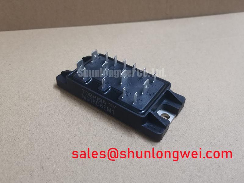
Toshiba MG15D6EM1 IGBT: Datasheet for Power Switching Design
Technical Overview of the MG15D6EM1 IGBT Module
The Toshiba MG15D6EM1 is an N-channel IGBT module engineered to provide a balanced performance profile for power conversion applications. This device is structured to mitigate total power loss by addressing both conduction and switching phases. It provides a robust foundation for systems where thermal management and operational efficiency are primary design considerations. How does the MG15D6EM1 balance performance? It combines a low saturation voltage with controlled switching characteristics, making it effective for medium-frequency power circuits.
- Core Specifications: 600V | 15A | VCE(sat) 3.5V max.
- Key Benefits: Reduced conduction losses. Simplified thermal design.
Key Performance Parameters of the MG15D6EM1
The operational characteristics of the MG15D6EM1 are defined by its electrical and thermal parameters. These values are critical for accurate system modeling, performance simulation, and ensuring long-term reliability. The following tables detail the absolute maximum ratings and the electrical characteristics as specified in the official datasheet. For comprehensive design work, please refer to the complete product documentation.
Download the MG15D6EM1 Datasheet for full specifications.
Absolute Maximum Ratings (Ta = 25°C)
| Parameter | Symbol | Rating | Unit |
|---|---|---|---|
| Collector-Emitter Voltage | VCES | 600 | V |
| Gate-Emitter Voltage | VGES | ±20 | V |
| Collector Current (DC) | IC | 15 | A |
| Collector Current (1ms) | ICP | 30 | A |
| Collector Power Dissipation (Tc = 25°C) | PC | 80 | W |
| Junction Temperature | Tj | 150 | °C |
| Storage Temperature Range | Tstg | -40 to 125 | °C |
Electrical Characteristics (Ta = 25°C)
| Parameter | Symbol | Test Condition | Min. | Typ. | Max. | Unit |
|---|---|---|---|---|---|---|
| Collector Cut-off Current | ICES | VCE = 600V, VGE = 0V | - | - | 1.0 | mA |
| Gate Leakage Current | IGES | VGE = ±20V, VCE = 0V | - | - | ±500 | nA |
| Gate-Emitter Cut-off Voltage | VGE(off) | IC = 1.5mA, VCE = 5V | 3.0 | - | 6.0 | V |
| Collector-Emitter Saturation Voltage | VCE(sat) | IC = 15A, VGE = 15V | - | - | 3.5 | V |
| Input Capacitance | Cies | VCE = 10V, VGE = 0V, f = 1MHz | - | 600 | - | pF |
| Turn-On Time | ton | Inductive Load, IC = 15A, VCC = 300V, VGE = ±15V, RG = 100Ω | - | - | 1.0 | µs |
| Switching Time (Storage) | tstg | - | - | 1.5 | ||
| Fall Time | tf | - | - | 0.5 | ||
| Thermal Resistance (Junction to Case) | Rth(j-c) | IGBT | - | - | 1.56 | °C/W |
Comparative Analysis for System Integration
When evaluating power modules, comparing key parameters provides a clear data-driven basis for selection. The MG15D6EM1's characteristics position it for specific types of applications. Below is a factual comparison to contextualize its performance. This data is intended to support, not direct, your component selection process.
- Voltage and Current Ratings: The MG15D6EM1 is rated for 600V and 15A. For systems operating at similar voltages but requiring higher current capabilities, a device such as the BSM50GP60 offers a 50A rating, representing a different point in the power-handling spectrum.
- VCE(sat) vs. Switching Speed: With a maximum VCE(sat) of 3.5V, this module is optimized for applications where conduction losses are a significant concern. The switching times (ton, tstg, tf) are moderate, suiting it well for low-to-medium switching frequencies where the low conduction loss provides a net efficiency benefit.
Strategic Value in Energy-Conscious Systems
The global push towards higher energy efficiency standards directly impacts component-level design choices. IGBTs like the Toshiba MG15D6EM1 are integral to meeting these evolving requirements. The module's performance, particularly its low VCE(sat), directly contributes to reducing the overall power consumption of the end system. This reduction in wasted energy not only lowers operating costs but also decreases the carbon footprint of the application, aligning with sustainability goals in industrial automation and power supply design.
A Closer Look at Switching and Conduction Dynamics
What defines the MG15D6EM1's efficiency? Its low 3.5V VCE(sat) minimizes conduction losses. This parameter, the Collector-Emitter Saturation Voltage, can be visualized as the electrical "friction" the device exhibits when it is fully on. A lower VCE(sat) is analogous to a water valve that opens wider, allowing current to flow with less resistance and, consequently, generating less heat. This efficiency in the 'on' state is crucial in applications like motor drives, where the IGBT spends a significant portion of its duty cycle conducting heavy current.
While minimizing conduction loss, the MG15D6EM1 maintains controlled switching times. The specified maximums for turn-on (1.0 µs) and fall time (0.5 µs) are critical for calculating switching losses, which become more prominent as operating frequency increases. The module's design represents a deliberate trade-off, prioritizing low conduction losses while providing adequate switching performance for a range of industrial power conversion tasks. For a deeper understanding of datasheet parameters, consider resources on decoding IGBT datasheets.
Application Focus: Where Efficiency Translates to Value
The technical specifications of the Toshiba MG15D6EM1 make it a viable component for a variety of power switching circuits where efficiency and thermal stability are key. Its characteristics are well-suited for:
- Small to Medium Motor Drives: In applications such as HVAC systems, pumps, and general-purpose industrial drives, the low conduction losses help reduce the size and cost of heatsinking, leading to more compact and economical designs.
- Power Supply Units (PSU): For switching power supplies and uninterruptible power supplies (UPS), the module's 600V rating provides sufficient voltage margin for systems running off rectified mains, while its efficiency contributes to higher overall PSU performance.
- Welding Equipment: The device's current handling capabilities are appropriate for the inverter stages of smaller welding power supplies.
For medium-frequency (<20kHz) motor drives, the MG15D6EM1's 3.5V VCE(sat) makes it a superior choice where conduction losses dominate the thermal budget.
Frequently Asked Questions
1. What is the primary engineering implication of the 3.5V maximum VCE(sat) for the MG15D6EM1?
A VCE(sat) of 3.5V at a nominal current of 15A points to a design optimized for minimizing conduction losses. This directly translates to lower heat generation during the on-state, simplifying thermal management and potentially allowing for smaller, more cost-effective heatsinks. It makes the device particularly suitable for applications with high duty cycles.
2. How should a designer approach thermal management for this IGBT module?
Effective thermal design starts with the Rth(j-c) value of 1.56 °C/W. An engineer must calculate the total power loss (conduction + switching) for their specific application conditions. This power loss, multiplied by the total thermal resistance from junction to ambient (including the thermal interface material and heatsink), will determine the junction temperature, which must be kept below the 150°C maximum rating. Resources covering IGBT thermal performance can provide further guidance.
Disclaimer: The technical information provided is based on publicly available datasheets. As a distributor, we do not provide design guarantees or warranties. All parameters should be verified by consulting the official manufacturer's documentation for your specific application.
For further evaluation or to request a quote, please contact our technical sales team to discuss your project requirements.