Content last revised on October 7, 2026
EVL31-060 Thermal Electrical Optimization: Active Miller Clamp Implementation Practical Tuning
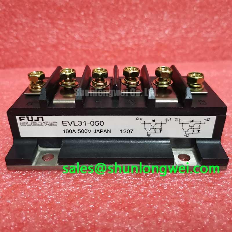
Begin bench evaluation by confirming the part marking, checking the module housing for visible damage, and verifying that the equipment documentation calls for a 600 V, 60 A Fuji Electric power module before applying any gate signal. The supplied product data identifies the EVL31-060 as a Fuji Power Module with a rated voltage of 600.0 V and a rated current of 60.0 A. Gate threshold, gate voltage range, short circuit withstand capability, switching energy, thermal resistance, and terminal assignment should be confirmed from the applicable Fuji Electric documentation before replacement or circuit modification.
For a commercial string inverter or micro grid energy storage converter, the practical objective is to keep the gate drive waveform clean while preventing unintended turn on during rapid collector voltage transitions. An active Miller clamp can be considered when the driver architecture supports it. This is a system level design consideration, not a confirmed internal feature of the EVL31-060. The clamp path should be physically close to the gate driver return path, with the power switching loop and gate loop kept separate wherever the board architecture permits.
Negative gate bias is sometimes evaluated in high dv/dt switching systems to improve off state immunity. The suitable value is determined by the gate driver, insulation arrangement, gate oxide limits, switching speed, and the complete module application circuit. The EVL31-060 product information supplied here does not establish a negative gate voltage rating, so designers should verify the original Fuji documentation before using any negative bias. A two channel oscilloscope measurement of gate to emitter voltage and collector to emitter voltage is appropriate during controlled switching tests.
When unexplained cross conduction appears, inspect the gate resistor path, driver return routing, common emitter impedance, isolated power supply behavior, and probe reference connection. A distorted waveform may indicate measurement pickup, driver saturation, parasitic coupling, or an actual gate control problem. Compare the suspect channel with a known good channel under identical operating conditions rather than assigning the symptom to the IGBT alone.
Design recommendation: Keep the active clamp connection and gate return physically compact, then validate the peak gate voltage and switching margin with a controlled double pulse test before connecting the full energy storage link.
Fuji Electric application information on brake chopper IGBT modules and its broader IGBT module portfolio can provide useful context for evaluating driver topology, switching behavior, and application boundaries. These references should not be treated as a substitute for the specific EVL31-060 datasheet.
Assembly Integrity and Layout Architecture: Implementing Thermal Feedback for EVL31-060
The EVL31-060 is identified by the supplied specifications as a Fuji Power Module rated at 600.0 V and 60.0 A. Mechanical integration should begin with the original equipment mounting pattern, terminal layout, insulation requirements, and cooling interface. The provided data does not include module dimensions, mounting torque, thermal resistance, or terminal geometry. Those values must be checked against the manufacturer documentation and the equipment service drawing rather than inferred from the model number.
In parallel switching arrangements, the positive temperature coefficient commonly associated with the on state voltage of an IGBT can support static current sharing. This should be treated as a design consideration, not as a guarantee that parallel devices will share current dynamically. Dynamic balance depends on matched gate loop impedance, symmetrical busbar geometry, equivalent emitter return paths, driver timing, and the transient behavior of the freewheeling path.
During assembly, inspect the mating surfaces for contamination, uneven contact, and mechanical distortion. Thermal interface preparation should follow the cooling system manufacturer’s process. Excess interface material, an uneven clamping sequence, or a warped heatsink can create local thermal resistance and produce a temperature pattern that is not visible from average heatsink temperature.
A freewheeling diode in the commutation path and its reverse recovery behavior can influence collector voltage overshoot, conducted noise, and radiated emissions. The EVL31-060 product data supplied for this page does not specify diode recovery charge or reverse recovery time. Engineers should therefore measure the actual commutation waveform with the intended DC link, gate drive, busbar, and load conditions. A snubber may be evaluated when the measured transient or ringing exceeds the system design limit, but its component values must be established through switching tests and loss assessment.
Use a low inductance power loop, avoid unnecessary conductor area in the high di/dt path, and maintain physical separation between high energy switching nodes and sensitive control traces. Clearance and creepage requirements are determined by working voltage, pollution environment, insulation category, altitude, and the applicable product standard. The module’s 600 V rating alone does not define the required board or busbar spacing.
For an active front end rectification stage associated with an inverter or storage converter, engineers may evaluate the 6MBI15L-060 as a separate module option. Compatibility must be checked at the topology, current, thermal, isolation, and control levels. It should not be assumed to be a direct substitute for the EVL31-060.
Preventing Spurious Faults: Four Quadrant Power Flow Topology Guidelines for EVL31-060
A bidirectional battery rack interface can command power flow in both directions, placing the switching devices under different combinations of current direction and voltage polarity. The EVL31-060 may be evaluated in such a converter when the system voltage, current, gate drive, cooling arrangement, insulation design, and switching frequency are compatible with its confirmed ratings. The available product information establishes the 600.0 V voltage rating and 60.0 A current rating only; it does not establish a complete four quadrant operating envelope.
Start the topology review by identifying which semiconductor conducts during charge, discharge, regenerative transfer, and freewheeling intervals. Then mark the physical current path on the schematic and compare it with the assembled busbar path. A mismatch between the electrical drawing and the physical conductor arrangement can produce unequal commutation behavior, unexpected circulating current, or excessive local heating.
In peak shaving service, repeated changes between battery charging and inverter support can create cyclic thermal loading. The correct evaluation method is to record junction temperature indicators, case temperature, current waveform, switching transition behavior, and cooling system response across the actual duty profile. A specific lifetime value or allowable thermal cycle count cannot be assigned without an authoritative reliability source and the relevant mission profile.
When a protection event occurs, inspect the event record together with the gate waveform, DC link voltage, phase current, and driver supply status. A fault flag may result from genuine overcurrent, supply disturbance, desaturation detection sensitivity, probe error, electromagnetic coupling, or timing interaction between protection channels. Repeating the test with reduced stored energy and a controlled current path can help separate a switching transient from a sustained fault.
Designers should also review isolation barriers and auxiliary power sequencing. The required supply voltage and timing must come from the original driver and module documentation. The EVL31-060 listing supplied here does not confirm a gate voltage, auxiliary supply voltage, logic threshold, or isolation specification.
For replacement assessment, the 3MBI50SX-120-02 may be reviewed as a separate Fuji Electric module option. A model comparison should include topology, voltage class, current rating, terminal arrangement, mechanical fit, thermal path, switching characteristics, and control compatibility. Similar package descriptions or current numbers are not sufficient to establish interchangeability.
EVL31-060 Thermal Electrical Optimization: High Speed Fault Management and VCE Desaturation Practical Tuning
Desaturation protection is commonly used to detect an IGBT condition in which collector to emitter voltage remains higher than expected during commanded conduction. Whether this method is suitable for the EVL31-060 depends on the driver circuit, sensing network, blanking behavior, isolation method, and the module’s documented short circuit characteristics. The supplied factory data does not confirm a desaturation threshold, short circuit safe operating area, or a guaranteed detection time.
A practical protection review should trace the complete path from the collector sensing point to the isolated driver fault output. Check the sensing diode orientation, filtering network, gate clamp behavior, fault latch operation, and reset sequence. During a controlled test, use a limited energy source and verify the collector voltage, gate voltage, current waveform, and driver response simultaneously. A slow or irregular turn off may reflect excessive loop inductance, driver current limitation, sensor delay, or a protection circuit that is reacting to normal switching recovery.
Two stage soft turn off can be considered when a direct, fast gate discharge would create excessive inductive voltage overshoot. The first stage reduces the conduction current under controlled gate action, while the later stage completes turn off according to the driver design. The timing and gate current must be selected by the system engineer after measuring the actual commutation loop and confirming the module’s short circuit limits from the applicable Fuji documentation. The figures sometimes used in generic IGBT guidance, including sub ten microsecond protection targets, must not be presented as an EVL31-060 factory specification without a supporting source.
Keep the fault sensing conductors away from high dv/dt copper, use a defined reference at the driver, and validate the measurement with an appropriate high voltage differential probe. If a fault occurs only at full DC link voltage, compare the sensed waveform with the switching node at the driver pins. If it occurs during low energy testing as well, inspect the sensing network, driver supply stability, and blanking arrangement before replacing the module.
The technical discussion at Wide Bandgap Revolution provides broader context on high speed switching and layout challenges. It does not establish operating limits for this silicon IGBT module. The final protection design remains dependent on the EVL31-060 documentation, the converter topology, measured switching transients, and the applicable safety requirements.