

Content last revised on October 11, 2026
Preventing Spurious Faults: Diagnosing Gate-Emitter Dielectric Faults in MG400G1UL1
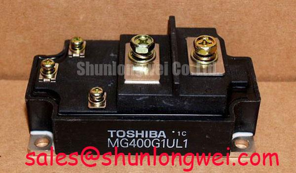
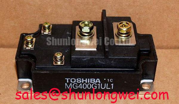
With the DC link isolated and verified discharged, disconnect the gate driver before checking the MG400G1UL1 power terminals in diode mode. Record both probe polarities and compare the results with the circuit diagram and a known-good assembly, rather than treating one meter reading as a pass certificate. The Toshiba MG400G1UL1 is an IGBT module with a 600 V voltage rating and 400 A current rating. These ratings are subject to the manufacturer’s specified conditions and do not by themselves establish suitable system operating limits.
Screen the gate-to-emitter path separately from the main current path so that driver resistors and protection components do not mask the measurement. As a Design Consideration, diode-mode testing can expose gross shorts or asymmetric conduction, but it cannot establish gate dielectric integrity under operating stress. Check the antiparallel diode path against the documented internal circuit; avoid assigning a universal forward-voltage threshold to every meter and module temperature.
Investigate unexpected gate readings with a suitable leakage measurement procedure that respects the manufacturer’s gate limits. A drifting resistance indication can reflect charging effects or connected circuitry, not necessarily damage. Keep gate terminals protected against electrostatic discharge throughout handling, and never apply a power-terminal insulation test directly across the gate.
Clean contamination around terminal barriers before evaluating creepage and clearance. As a Design Consideration, required spacing depends on working voltage, pollution conditions, insulation coordination, and the equipment construction. Moisture or conductive deposits warrant inspection of the enclosure and airflow path, not an improvised acceptance threshold. Establish maintenance intervals from operating conditions and inspection history rather than assigning an unsupported calendar life to the module.
Field Diagnostics & Commissioning: Replacement Retrofit: Tuning Turn-On/Turn-Off in MG400G1UL1 Topologies
Evaluate external turn-on and turn-off gate resistance independently when commissioning a replacement assembly. As a Design Consideration, increased damping can reduce oscillation while extending switching transitions; lower resistance can increase switching speed and overshoot. Observe gate-to-emitter voltage, collector voltage, and switching current together, then assess losses and protection behavior across the intended operating range.
Include Miller charge and reverse-transfer capacitance in the driver assessment rather than relying on gate resistance alone. An active Miller clamp, where supported by the driver, requires a short return path and verification during opposing-switch transitions. Set dead time from actual device and driver timing over temperature; an arbitrary delay can either leave overlap risk or unnecessarily increase diode conduction.
Where the existing high-side driver uses a bootstrap supply, assess capacitance from total charge demand during the longest interval without recharge. Include gate charge, driver quiescent consumption, leakage, capacitor tolerance, and permissible supply droop. This is a Design Consideration for the driver circuit, not an MG400G1UL1 capacitor prescription. A separately powered isolated driver needs a different supply assessment.
Compare MG50Q1BS1 only through a documented replacement review; the link does not establish drop-in compatibility. Likewise, MG75G1JL1 can be reviewed alongside the system schematic without assuming a rectifier role or shared drive requirements. Consult the manufacturer’s datasheet for terminal assignments, gate limits, switching characteristics, and mechanical compatibility before substitution.
Preventing Spurious Faults: Transmission Line Impedance Mismatch Guidelines for MG400G1UL1
Measure inverter-output and motor-terminal waveforms separately when long motor leads accompany intermittent faults. As a Design Consideration, cable reflections can produce motor-terminal peaks approaching twice the incident voltage step under strong positive reflection conditions. That relationship is not an MG400G1UL1 terminal-voltage specification and should not be confused with local collector overshoot caused by commutation inductance.
Evaluate output reactors or dv/dt filters against cable characteristics, motor insulation requirements, switching frequency, and load current. Confirm their effect at both ends of the cable using appropriately rated differential probes. Keep measurement loops compact and account for probe bandwidth before interpreting ringing as a device fault.
Protection coordination remains a separate task: the Mersen Protistor® High Speed Semiconductor Protection Fuses resource provides context for semiconductor fuse selection, but a fuse does not suppress reflected-wave voltage. For topology context, Peak Efficiency in Solar and Energy Storage is supplementary reading, not evidence of this module’s lifetime or application qualification.
Transient Dynamics & Electrical Design: Auxiliary Kelvin Emitter vs Main Power Emitter on MG400G1UL1
Trace the driver return against the terminal drawing before assigning any auxiliary connection a Kelvin-emitter function. A dedicated Kelvin emitter is not established by the supplied MG400G1UL1 package information. Where the documented connection provides a separate emitter return, route the driver loop independently of the load-current path to reduce shared-inductance voltage disturbances.
As a Design Consideration, parallel assemblies also require balanced power connections, gate paths, and cooling; a favorable temperature coefficient alone does not establish dynamic current sharing. For a high-speed rail or heavy freight locomotive traction-inverter assessment, confirm converter voltage class, topology, and equipment qualification before considering this module. JEDEC Solid State Technology Association Standards provide test-method context, not railway approval.
Maintenance Note: Trend terminal temperature under comparable load, check airflow and thermal-interface condition, and verify terminal tightening against the equipment’s specified procedure during isolated maintenance.