Content last revised on July 10, 2026
An Engineer's Review of the MG8N6ES40: A Focus on High-Speed Switching Performance
Engineering-Grade Introduction and Key Highlights
Optimized for Efficiency in High-Frequency Power Conversion
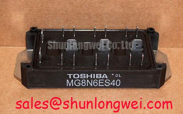
The Toshiba MG8N6ES40 is an N-Channel Insulated Gate Bipolar Transistor (IGBT) designed to deliver reliable performance in high-speed switching applications. It establishes a critical balance between switching efficiency and conduction losses, making it a functional choice for power conversion circuits where performance and thermal management are key design drivers. With core specifications of 600V and 8A, this device offers a robust foundation for power stage design. Key engineering benefits include enhanced power conversion efficiency and simplified thermal design. For engineers developing compact and efficient motor drives or power supplies, the MG8N6ES40 provides a well-defined performance profile. Best fit for cost-sensitive, high-frequency applications under 5kW where minimizing switching losses is a primary objective.
Application Scenarios & Value
Achieving System-Level Benefits in Compact Power Systems
The MG8N6ES40 is engineered for applications where switching speed directly correlates to system size, efficiency, and cost. Its primary value is demonstrated in systems operating at higher frequencies to reduce the size of magnetic components like inductors and transformers.
A high-fidelity engineering scenario for this IGBT is in the inverter stage of a fractional horsepower Variable Frequency Drive (VFD) or a small uninterruptible power supply (UPS). In these applications, the ability to switch quickly and cleanly minimizes energy lost as heat during the on/off transitions. This lower switching loss, a hallmark of the "ES" (High-Speed Switching) series, allows designers to either push for higher operating frequencies for a more compact design or to reduce the requirements for the system's heatsink, leading to a smaller physical footprint and lower bill-of-materials (BOM) cost. What is the primary benefit of its fast-switching design? It enables higher system efficiency and reduces thermal management costs.
While the 8A current rating is well-suited for smaller loads, for systems requiring control of larger motors or higher power throughput, a component with a greater current capacity would be necessary. For instance, the MG10Q6ES50A offers a higher rating of 1200V and 10A, making it suitable for more demanding industrial applications.
Key Parameter Overview
Decoding the Specs for Efficient Power Stage Design
The technical specifications of the MG8N6ES40 are foundational to its performance in power circuits. The parameters listed below are derived from available technical documentation and provide a clear view of its operational capabilities. Highlighting the key metrics allows for a focused evaluation for specific design requirements.
| Parameter | Value | Engineering Significance |
|---|---|---|
| Collector-Emitter Voltage (Vces) | 600V | Provides a sufficient voltage margin for applications running on 230V/400V AC lines, ensuring reliability against voltage spikes. |
| Collector Current (Ic) | 8A | Defines the device's continuous current handling capability, suitable for low-to-medium power applications. |
| Technology Generation | ES-Series (High-Speed) | Indicates the device is optimized for low switching losses (Eon, Eoff), which is critical for high-frequency operation. |
| Collector-Emitter Saturation Voltage (Vce(sat)) | Typ. 2.7V | A key factor in conduction losses. This value represents a trade-off for achieving the component's high switching speed. |
| Package | TO-220SIS (Isolated) | The integrated isolation simplifies mounting to a heatsink by eliminating the need for an external insulating pad, which can streamline assembly. |
Technical Deep Dive
The Engineering Trade-Off: Balancing VCE(sat) and Switching Speed
At the core of any IGBT selection is the fundamental trade-off between conduction loss and Switching Loss. The MG8N6ES40, as part of a high-speed series, is intentionally designed to favor lower switching losses. This is achieved by techniques that reduce the 'tail current' during the turn-off phase, enabling faster transitions. Think of switching loss like a leaky faucet: every time you turn the water on or off, a little bit drips out. In a high-frequency system, you're turning it on and off thousands of times per second, and those drips (lost energy) add up quickly to a significant amount of wasted power and heat.
Conversely, this optimization for speed often results in a slightly higher Collector-Emitter Saturation Voltage (VCE(sat)), which dictates conduction loss—the energy lost while the switch is fully on. A higher VCE(sat) is like having a slightly narrower pipe; it creates more resistance to the flow. For an application like a VFD where the IGBT is constantly switching, the energy saved by plugging the 'leaks' (low switching loss) often outweighs the energy lost to the 'narrower pipe' (higher VCE(sat)). The MG8N6ES40's specification set points directly to its suitability for such dynamic, high-frequency environments over applications that involve long periods of static conduction. For more on this topic, explore this guide to IGBT selection for high-frequency designs.
Frequently Asked Questions (FAQ)
What does the "ES" designation in the MG8N6ES40 part number signify for my design?
The "ES" identifies this IGBT as part of Toshiba's High-Speed Switching series. This means it is engineered to minimize energy losses during turn-on and turn-off events (Eon and Eoff). For a design engineer, this implies the device is optimized for higher-frequency applications (typically >15 kHz), where reducing switching losses is more critical to overall efficiency than minimizing conduction losses.
How does the 600V Vces rating influence the suitability for specific industrial line voltages?
A 600V rating provides a standard safety margin for systems operating on a 230V single-phase or up to a 240V three-phase AC line. It offers protection against typical line transients and back-EMF from inductive loads like motors. However, it is not suitable for 480V or 690V AC industrial lines, which would require IGBTs with ratings of 1200V or 1700V, respectively.
Given its high-speed nature, are there specific gate drive considerations for the MG8N6ES40?
Yes. To achieve the specified fast switching times and prevent issues like parasitic turn-on, a properly designed Gate Drive circuit is crucial. This includes using a low-impedance driver capable of sourcing and sinking adequate peak current, keeping gate traces short to minimize inductance, and potentially using a negative gate voltage during the off-state to ensure a robust turn-off, especially in noisy environments.
What is the typical impact of the TO-220SIS isolated package on thermal design?
The TO-220SIS package features an electrically isolated mounting tab. This simplifies manufacturing by allowing the device to be mounted directly to a common heatsink without needing a separate insulating thermal pad and bushing. While this speeds up assembly, engineers must use the specified thermal resistance from junction-to-case (Rth(j-c)) for this isolated package in their thermal calculations, as it will be slightly higher than a non-isolated equivalent. This is a key parameter in ensuring the device operates within its safe temperature limits. A deeper understanding of this can be found in our analysis of IGBT reliability and failure modes.
Strategic Design Considerations
Selecting the MG8N6ES40 is a strategic decision for projects where the design priorities are locked on high-frequency efficiency and BOM cost optimization in the low-to-medium power range. Its characteristics are representative of a specific generation of IGBT technology, offering a proven and cost-effective solution for applications whose life cycles do not demand the absolute lowest losses provided by the latest trench-gate or SiC technologies. For new designs, engineers must weigh the established reliability and performance of this device against the potential long-term efficiency gains and higher power density offered by newer, more advanced components.