
Content last revised on October 23, 2026
MMF2X100J040D Operational Boundaries: Evaluating High-Frequency Switching Loss Dissipation Limits
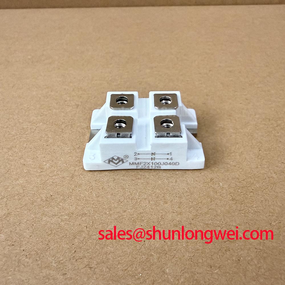
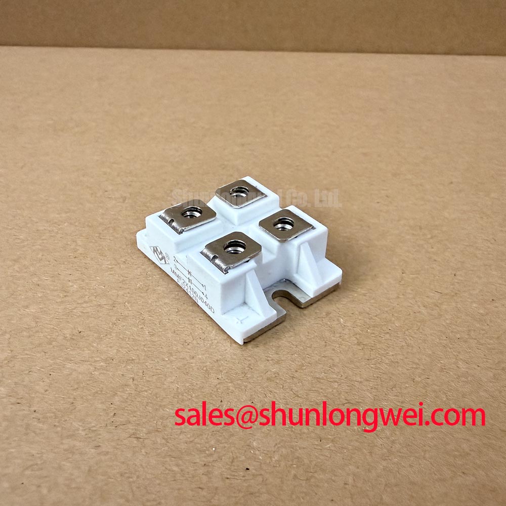
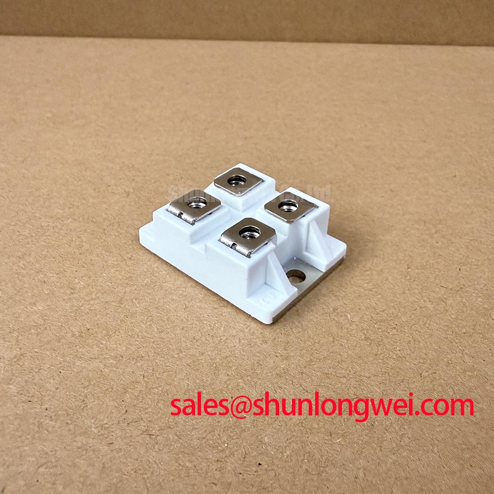
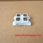
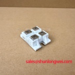
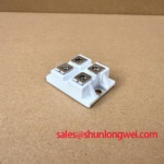
I map the MMF2X100J040D terminal markings to the equipment schematic before checking forward conduction with a multimeter. With the module isolated from parallel circuit paths, I record diode-mode readings in both probe directions and compare equivalent paths at a consistent temperature. These readings support incoming inspection; they do not establish rated forward voltage, reverse blocking capability, or switching performance.
Design Consideration: Reverse recovery matters when the surrounding circuit forces a conducting diode into reverse bias. Peak reverse recovery current and recovery time must be read together with their specified forward current, commutation rate, reverse voltage, and junction temperature. A recovery-time figure alone does not establish soft recovery or predict switching loss. For this module, a numerical recovery claim belongs alongside the corresponding manufacturer test conditions.
During equipment evaluation, capture diode current and terminal voltage with appropriately rated instrumentation. Examine the recovery tail, voltage overshoot, and ringing under representative operating conditions. Minimize the commutation-loop area to reduce parasitic inductance, then validate the result at the actual terminals. Lower ringing does not independently establish equipment EMC compliance.
Protection review should compare the fuse manufacturer’s total-clearing I²t information with the module’s applicable surge withstand specification, including waveform and temperature conditions. Installation review should separately check the specified terminal torque and mounting torque rather than treating them as interchangeable. Powerex High Power Semiconductor Modules provides broader power-semiconductor technical context, not substitute MACMIC specifications.
💡 Bench Tip: Use ESD-safe handling and compare cold-state readings only after isolating the module and verifying that stored circuit energy has discharged.
MMF2X100J040D Thermal-Electrical Optimization: AC-to-DC Transfer Characteristics and Practical Tuning
Separate diode conduction from thyristor firing-angle control before interpreting an AC-to-DC test. The MMF2X100J040D is identified here as a diode module; a diode does not accept a firing-angle command. Any controlled transfer characteristic belongs to the surrounding converter topology and its controlled devices, not to an assumed gate function on this component.
Design Consideration: In a phase-controlled rectifier, changing firing angle changes the available average DC voltage, while load inductance and continuity of current influence the measured response. Delayed conduction can increase displacement-related reactive demand, and distorted line current adds a separate power-factor penalty. Those effects require simultaneous input-power and output measurements rather than a transfer curve inferred from the diode’s part number.
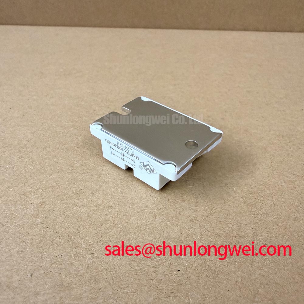
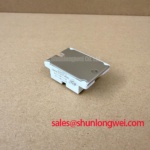
For thermal evaluation, relate measured conduction intervals and current waveforms to the manufacturer’s forward-characteristic curves and thermal limits. Check heatsink contact condition, mounting flatness, and the approved interface material before attributing elevated temperature to the semiconductor. Polyphenylene Sulfide (PPS) is background reading on an engineering polymer; it does not establish the housing material or temperature rating of this module.
Replacement assessment should compare terminal arrangement, blocking rating, current-rating conditions, recovery behavior, and mechanical fit. The ATMEL-CORPORATION catalog is a separate component reference, not evidence of a compatible replacement. Matching a broad category or package description is insufficient to approve substitution.
Transient Dynamics & Electrical Design: 6-Pulse and 12-Pulse Bridge Configurations on MMF2X100J040D
Trace each bridge arm and transformer secondary connection before assigning the MMF2X100J040D to a rectifier assembly. Six-pulse and twelve-pulse describe system arrangements, not a verified internal circuit configuration for this module. Establish the actual terminal connections from the manufacturer’s circuit diagram before assembling a bridge.
Design Consideration: A twelve-pulse arrangement uses appropriately phase-displaced supplies and coordinated bridge connections to reduce selected input-current harmonics under suitable balance conditions. Where parallel bridges use an interphase transformer, current sharing depends on transformer characteristics, bridge voltage balance, and connection impedance. Kiloampere-level output cannot be inferred from a module designation or achieved safely by simply paralleling terminals.
A high-current green hydrogen electrolyzer DC power rectifier is one potential compatibility-assessment context, subject to its electrical, cooling, protection, and connection requirements. Engineers should evaluate the complete bridge duty rather than assign that application to this module without qualification.
Keep inverter-output cable reflections separate from rectifier commutation overshoot. If the equipment also includes a motor inverter, assess cable-related reflections at that subsystem; select any output filtering through its system-level validation. For an associated operator-display fault, The Ultimate Guide to Industrial TFT LCD Technology addresses the display subsystem, not diode qualification. At the rectifier itself, investigate unequal branch currents through connection resistance, cooling conditions, and synchronized waveform measurements before changing busbar geometry or protection settings.