

Content last revised on September 20, 2026
MTC110A1800V Identification and Replacement Checks
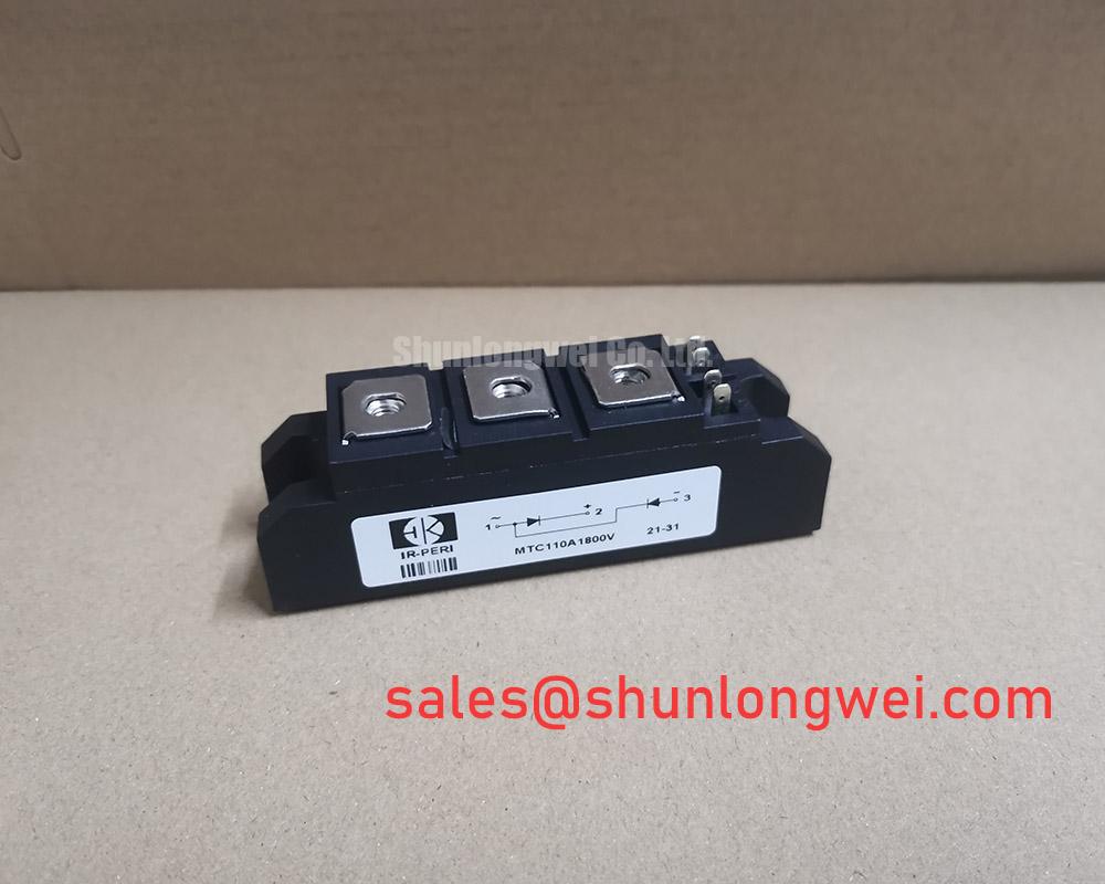
With the cabinet isolated and discharged, first compare the installed module marking, terminal arrangement, cold-state electrical readings, and mounting footprint against the replacement record before fitting MTC110A1800V. This SanRex (Sansha Electric) power module is officially rated at 1800V and 110A, supplied in a SanRex Power Module housing. Those ratings define the electrical identity to preserve during a repair of a high-voltage three-phase motor solid-state soft starter; they do not by themselves establish the correct fuse, surge network, thermal interface, or controller configuration.
Before removing a suspect unit, document each power connection and control lead at the original location. A multimeter check can reveal an obvious low-resistance power-path fault or an open connection, but it cannot validate dynamic commutation behaviour under load. Compare readings with the corresponding position in a known healthy phase where available, and keep the original equipment documentation available for terminal designation and gate-drive verification. The system integrator should verify the required trigger and control interface from the original soft-starter documentation.
| Identification item | Declared value | Classification |
|---|---|---|
| Product model | MTC110A1800V | Product identification |
| Manufacturer | SanRex (Sansha Electric) | Product identification |
| Rated voltage | 1800V | Official Specification |
| Rated current | 110A | Official Specification |
| Package | SanRex Power Module | Official Specification |
Preventing Spurious Faults: AC Line Surge Immunity and Lightning Transients for MTC110A1800V
On a stopped soft starter, inspect the incoming line protection before treating the module as the sole fault location. Cracked MOV bodies, darkened snubber components, loose line terminals, damaged insulation barriers, and heat-discoloured fuse hardware can all indicate that an overvoltage event or connection problem affected the phase assembly. The 1800V official voltage rating is a module boundary, not a statement that the installed equipment can tolerate every line transient without coordinated external protection.
As a Design Consideration, surge immunity in an AC-fed power controller depends on the complete protection path: incoming fusing, MOV clamping behaviour, RC snubber condition, conductor routing, earthing, and the voltage stress applied at the semiconductor terminals. IEC 61000-4-5 is commonly used as a system-level surge test reference, but no standalone system compliance claim should be inferred for this module. When restoring a soft starter, engineers should compare the original MOV and RC network part values with the equipment service documentation and investigate why any protection component has changed appearance or failed.
Fuse coordination also needs evidence from the original circuit documentation. The available product identification confirms 110A rated current, but it does not provide a published fuse I²t coordination value in the supplied technical data. Do not select a replacement fuse from module current alone. The protective device must be checked against the actual fault-clearing duty, conductor capacity, controller topology, and the equipment manufacturer’s protection requirements.
Power terminals deserve the same attention as surge parts. A terminal that has loosened through thermal cycling can create local heating and transient voltage disturbance that resembles a semiconductor failure. Clean only as permitted by the equipment maintenance procedure, confirm flat mating surfaces, and restore every washer, spacer, and insulating barrier in its documented order. ⚠️ Field Alert: Apply mounting and terminal torque only to the original equipment specification, because excessive force can distort the module while insufficient force can raise connection resistance.
For a broader engineering discussion of switching-energy management and test discipline in industrial drive equipment, see Unlocking Efficiency in Industrial Drives. The article is useful as a testing reference, while the voltage, current, terminal layout, and protection requirements for MTC110A1800V must remain specific to the actual soft-starter design.
MTC110A1800V Circuit Protection and Reliability: Reverse-Recovery Considerations
Commutation faults should be examined with care because a static meter test cannot measure reverse-recovery peak current, reverse-recovery time, charge, or recovery softness. No values for Irrm, trr, reverse-recovery charge, temperature coefficient, or switching-loss performance are established in the supplied official data for MTC110A1800V. These characteristics must therefore be obtained from the applicable manufacturer documentation or observed in a properly controlled system test; they must not be assumed from the 1800V and 110A ratings.
In a three-phase solid-state soft starter, commutation-related stress can be influenced by AC waveform conditions, phase firing sequence, load condition, snubber integrity, and wiring inductance. A Design Consideration is to inspect gate-command timing and line-to-line voltage behaviour with suitably rated instruments, using a known-good phase or a documented reference waveform where practical. An irregular waveform may indicate several possible issues, including controller timing, gate-circuit interruption, damaged suppression hardware, supply imbalance, or a stressed module. It should not be assigned to one cause without verification.
Current measurement is particularly useful when a repair has passed cold checks but behaves unpredictably under controlled energisation. The measurement path must have adequate isolation, bandwidth, placement, and fault withstand for the installation. ADI current-sense amplifier resources provide useful background on current-signal acquisition, although the sensing method and safety arrangement remain system-determined.
Do not add a bootstrap capacitor or substitute a high-frequency diode merely because those parts are common in other power converter topologies. The supplied information does not identify bootstrap circuitry as a feature of this SanRex module. If a soft-starter controller board contains an auxiliary supply, trigger transformer, isolated driver, or other pulse-conditioning circuit, its capacitor charging duty and diode recovery requirements must be verified from that controller’s original documentation and measured operating conditions.
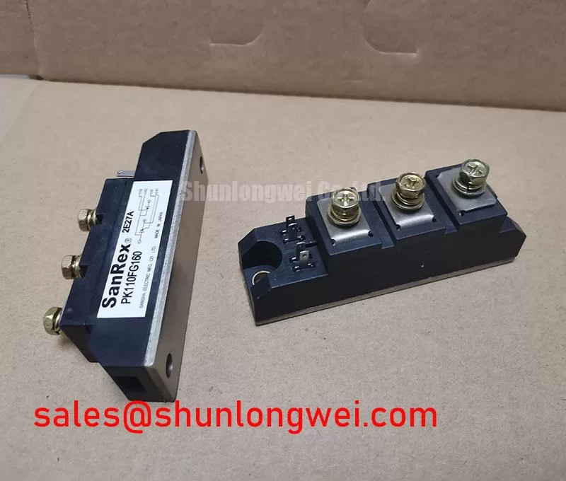
Where an adjacent device is being reviewed during a wider repair, PK55FG120 can be consulted as a separate power-semiconductor reference for the associated front-end or auxiliary-stage assessment. It is not a declared replacement for MTC110A1800V, and electrical, mechanical, and control compatibility must be established independently.
Transient Dynamics and Electrical Design: Junction-to-Heatsink Heat Dissipation for MTC110A1800V
Before installing the replacement module, inspect the heatsink for burrs, corrosion residue, embedded debris, and local distortion around the fastener holes. The thermal condition of the assembly is controlled by the complete contact stack, not by the module’s current rating alone. Although MTC110A1800V is officially rated at 110A, the supplied data does not state junction-to-case thermal resistance, case-to-heatsink resistance, maximum junction temperature, baseplate flatness, or an approved thermal-interface thickness. Those items must not be created as product specifications.
As a Design Consideration, use the thermal-interface material specified by the equipment manufacturer and apply it evenly enough to fill microscopic surface irregularities without creating a thick insulating layer. Position the module correctly before final tightening, follow the documented bolt sequence, and avoid forcing a housing to conform to an uneven heatsink. After service, check that the fan path, ducting, heat sink fins, and temperature-feedback wiring are in the same functional condition as before the fault.
A rising cabinet temperature or a recurring overload indication can originate in several places: restricted airflow, a degraded fan, incorrect thermal-sensor feedback, high connection resistance, repeated overload duty, or an altered firing pattern. Inspecting these conditions alongside the module prevents a replacement from being exposed to the unresolved cause. During controlled commissioning, compare phase current and thermal response using the equipment’s approved test method, rather than relying only on a brief no-load start.
When evaluating a physically similar power assembly, engineers sometimes review FRS200CA100 as a separate SanRex-family reference. This is a neutral comparison point only. Its electrical ratings, circuit function, package dimensions, terminal pattern, trigger requirements, and thermal arrangement must be checked against the original design before any procurement or installation decision.
Preventing Spurious Faults: Thermal and High-Peak Current Guidelines for MTC110A1800V
High-current half-cycle events require a disciplined review of the original protection chain. The supplied official information confirms 1800V rated voltage and 110A rated current, but it does not provide an official sinusoidal 10 ms half-cycle surge-current rating, an avalanche rating, a repetitive overload rating, or a junction-temperature limit for MTC110A1800V. These values must be taken from the applicable official datasheet before they are used in a repair decision or a protection review.
For this reason, it is not technically sound to infer surge capability from the module’s nominal current. A short-duration current event can be affected by upstream protection clearing time, motor starting profile, AC source impedance, firing command behaviour, heatsink temperature, and the condition of parallel mechanical connections. Engineers should examine event records where available, inspect the fuse and suppression network, and verify phase-current symmetry during an approved controlled test. Reverse voltage should only be reapplied after the equipment’s prescribed discharge, interlock, and restart procedure has been completed.
As an Engineering Recommendation, retain the original coordination between module, fuse, snubber network, gate-control board, and heatsink rather than modifying one part in isolation. This approach helps distinguish whether an apparent module fault is associated with line disturbance, commutation conditions, thermal transfer, or a controller-level command issue. The final acceptable operating margin is determined by the complete soft-starter system and must be verified against its documented electrical and thermal limits.