Content last revised on September 20, 2026
SSA500AA160 Thermal Electrical Optimization: Sinusoidal Surge Current Practical Tuning
| Manufacturer | SanRex (Sansha Electric) |
|---|---|
| Product Category | Thyristor / Diode Module |
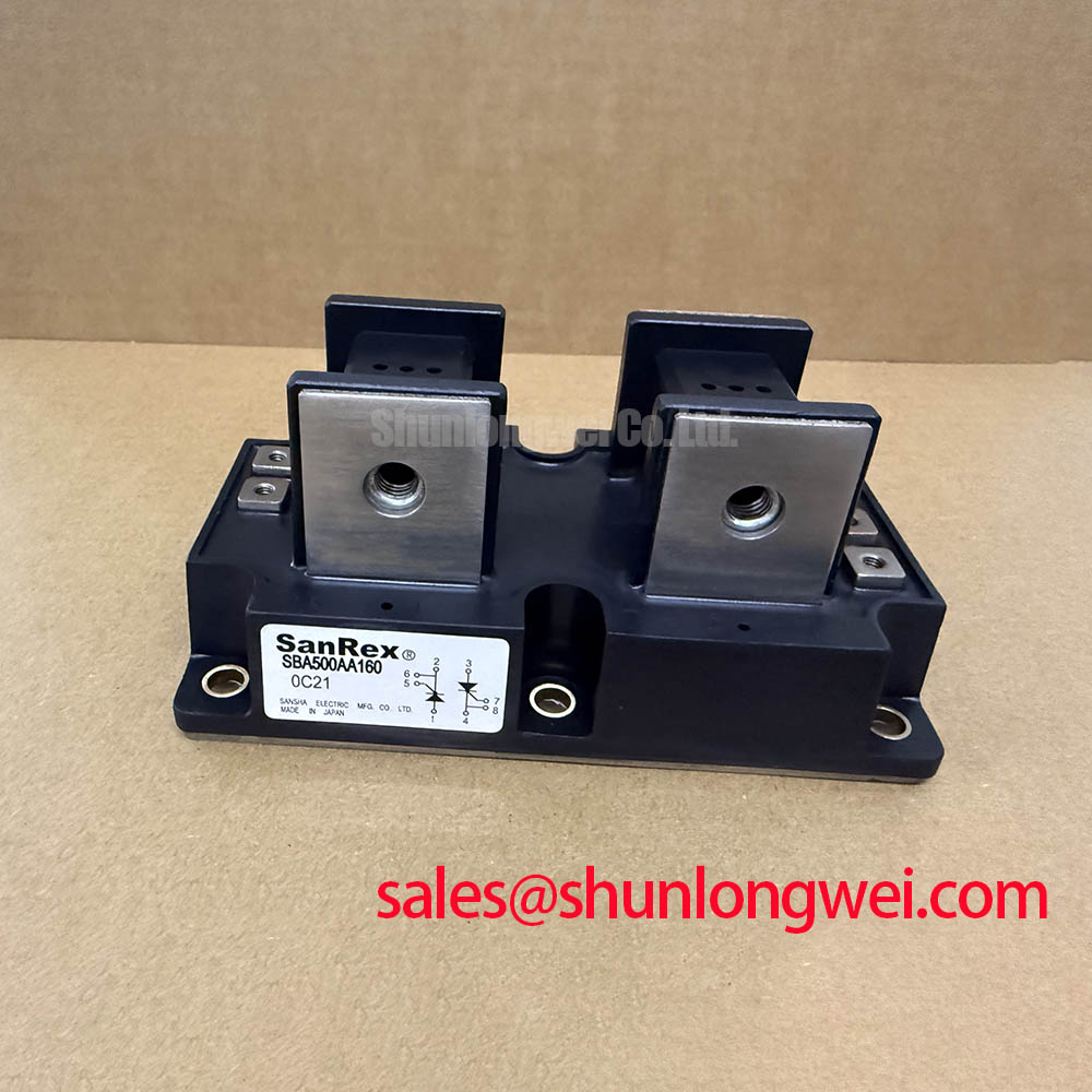
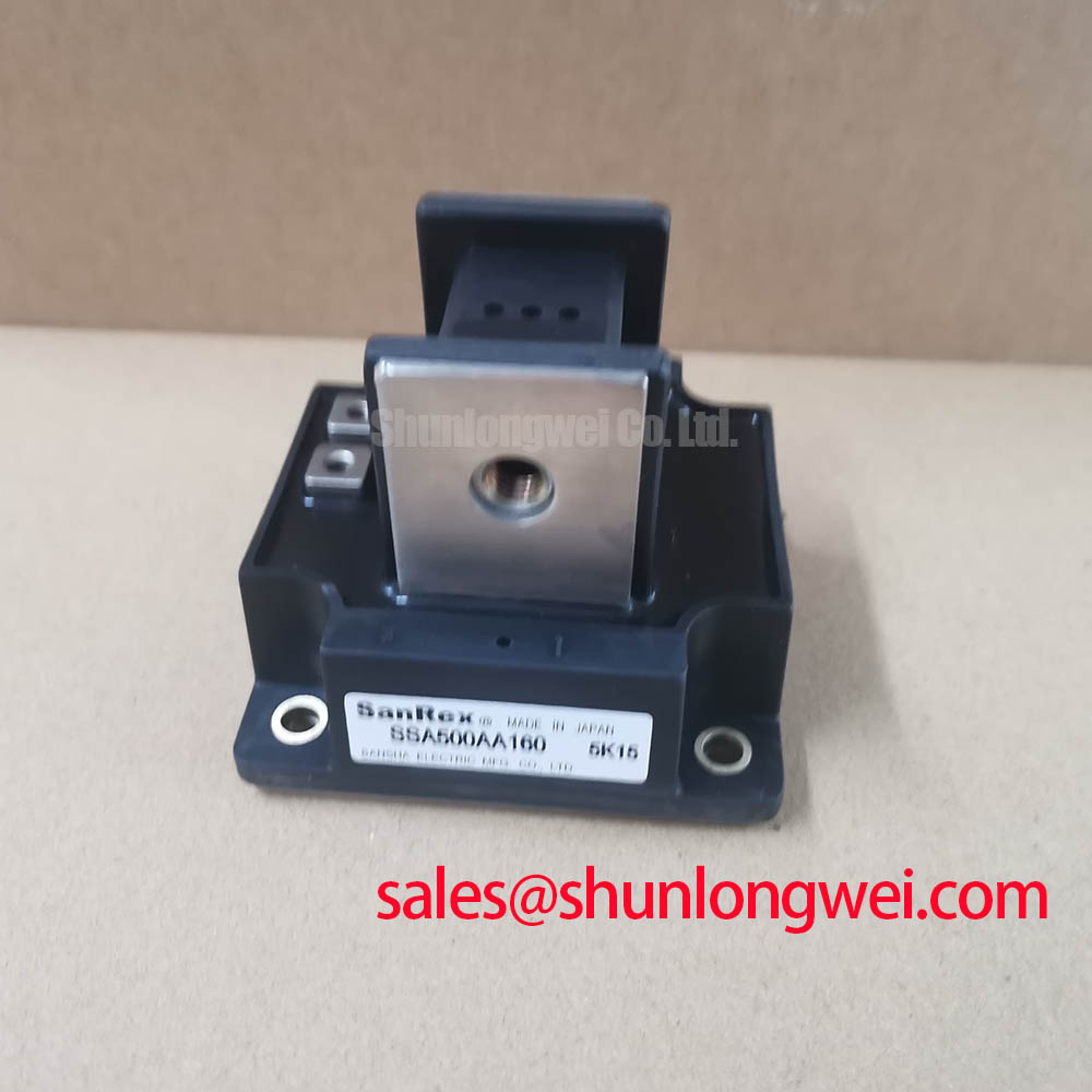
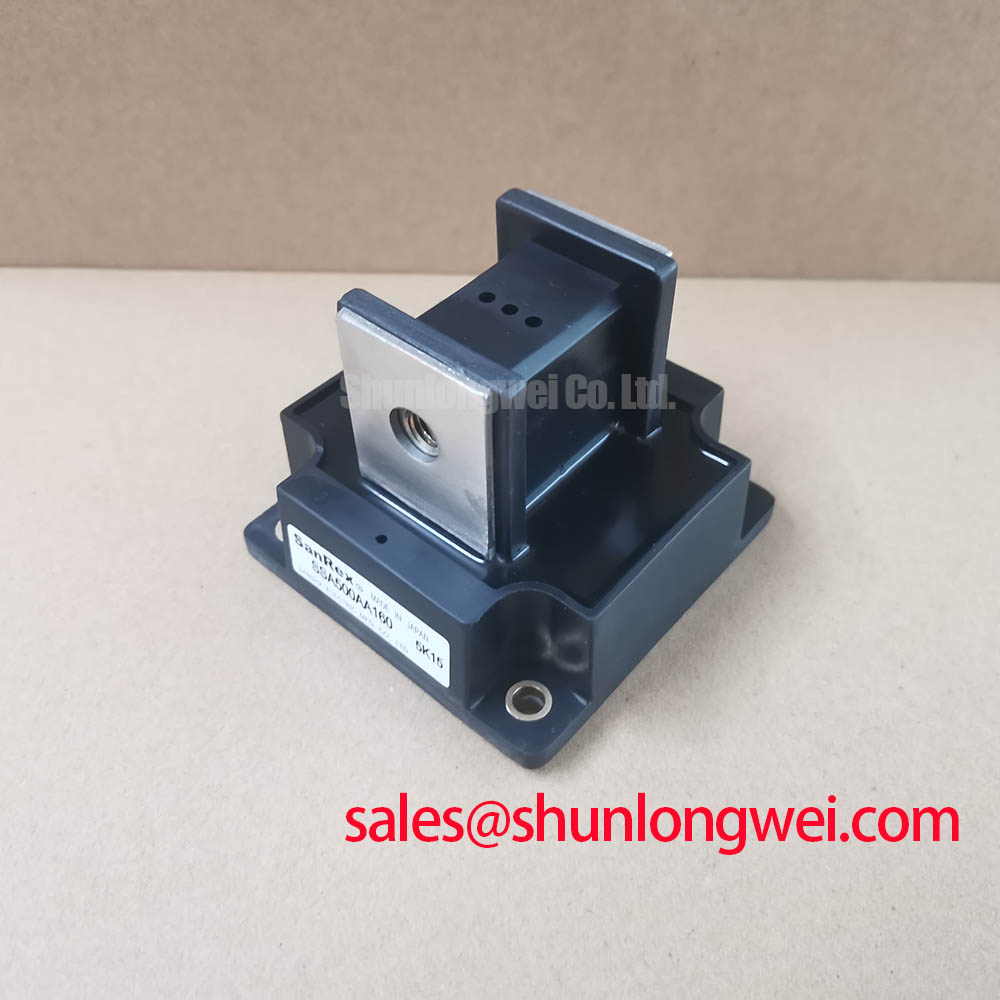
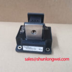
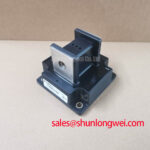
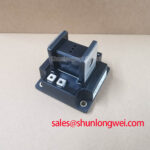
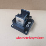
| Model | SSA500AA160 |
| Repetitive Peak Reverse Voltage | 1600 V |
| Average Forward Current | 500 A at Tc = 101°C |
| RMS Forward Current | 785 A |
| Surge Forward Current | 15000 A, 50 Hz, one non-repetitive cycle |
| Junction to Case Thermal Resistance | 0.075°C/W |
| Specified Junction Temperature Range | −40°C to 150°C |
Capture the current waveform at the rectifier input and confirm that any observed fault surge is assessed against the 15000 A non-repetitive surge current rating, specified for one 50 Hz cycle. This is an Official Datasheet Specification, not a continuous current capability. A recorded half-cycle waveform, repeated fault pulse, or transformer inrush event must be evaluated according to its actual duration and recurrence before the equipment is returned to service.
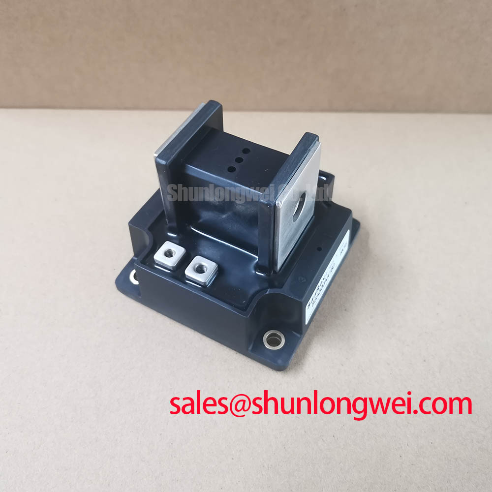
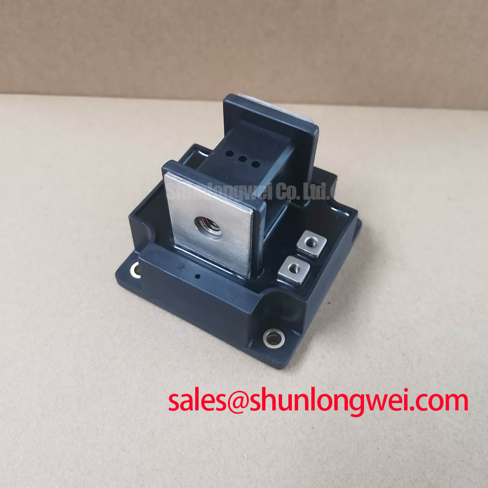
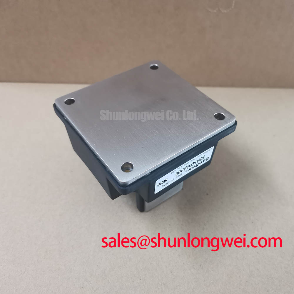
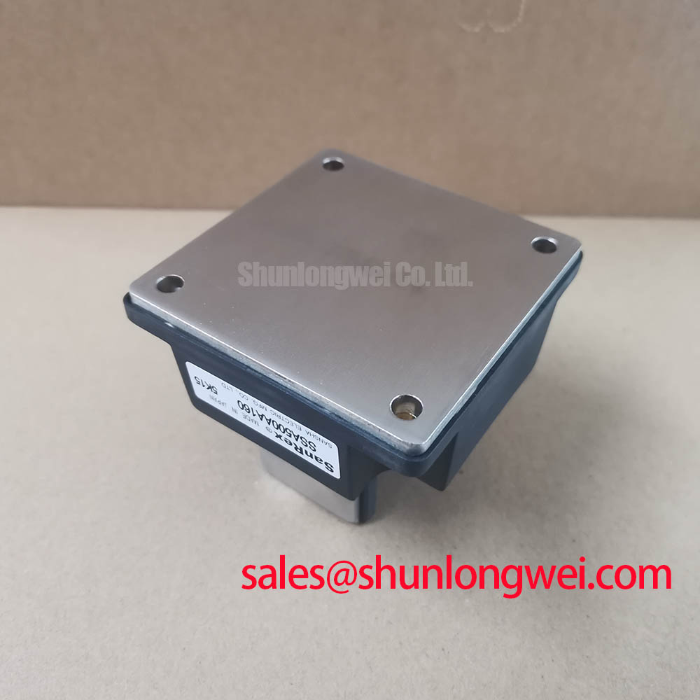
The SSA500AA160 carries an average forward current rating of 500 A at case temperature 101°C, with an RMS forward current rating of 785 A. In a medium-frequency induction melting or hardening furnace supply, measure the case temperature near the module mounting area during a stable production run and compare operating conditions with the stated current and temperature boundaries. The junction-to-case thermal resistance is 0.075°C/W, an Official Datasheet Specification that makes flat heatsink contact, clean mating surfaces, and uniform clamping important to thermal repeatability.
⚠️ Field Alert: Isolate the power source and confirm stored energy has been discharged before loosening any high-current terminal connection or removing the module from its heatsink.
Where the assembly uses M5 hardware, a 2.5 to 3.5 N·m tightening range is a General Industry Design Consideration rather than an official mounting specification for this model. The responsible engineer should verify the actual terminal hardware, conductor lug construction, and equipment drawing before applying torque. Uneven fastening can create local contact resistance that appears as a thermal problem during heavy-current operation.
SSA500AA160 Circuit Protection & Reliability: Calibrating Short-Circuit Withstand Limits and Coordination
Compare the semiconductor fuse pre-arcing and total-clearing I²t data with the module’s stated 1125 × 10³ A²s one-cycle surge withstand value before approving a fuse coordination plan. That figure is an Official Datasheet Specification for the SSA500AA160 and provides the device-side boundary for a fault study. The fuse manufacturer’s time-current and clearing curves remain necessary because prospective fault current, source impedance, busbar inductance, and clearing behavior are determined by the complete system.
Do not treat the surge number as a guarantee of damage-free dead-short interruption. A short circuit may involve asymmetric current, multiple pulses, arcing connections, or a supply that continues feeding after the first half-cycle. Engineering Recommendation: document the available fault current at the module terminals, then review the fuse-clearing energy under that measured or calculated condition against the module rating. Inspect fuse clips, busbar joints, and terminal lugs for heat discoloration or loss of clamping force after any protection event.
For bench incoming checks, disconnect the module from parallel paths and use a meter diode function across the accessible power terminals. Record forward-polarity response and reverse-blocking behavior as a cold reference for identical incoming units. A result that differs from the expected circuit path can arise from external suppression parts or parallel semiconductors, so verify the isolated module rather than assigning a single cause from an in-circuit measurement.
💡 Bench Tip: Use ESD-controlled handling and retain the first cold-state diode test record, because later comparisons are more useful when made with the same meter and lead polarity.
Transient Dynamics & Electrical Design: AC Input Transient Overvoltage Clamping on SSA500AA160
Probe the voltage directly across the rectifier connection during switching and line-disturbance testing to determine whether transient peaks approach the 1600 V repetitive peak reverse voltage rating. This rating is an Official Datasheet Specification. Probe placement matters: long ground leads and remote measurement points can show ringing that does not represent the voltage at the module terminals.
Metal oxide varistors, RC networks, transformer leakage inductance, cable routing, and incoming AC contactor behavior all influence the voltage seen by the device. Design Consideration: select and validate surge suppression from the measured source waveform, the protection coordination study, and the required repetitive duty. The system engineer should verify clamping behavior during representative switching and disturbance tests rather than assigning a universal MOV or snubber value to this module.
Transient control also depends on tight, mechanically secure power connections. Keep the commutation path compact where the equipment layout permits, particularly when suppressing inductive overshoot at current interruption. If a maintenance investigation includes control display or monitoring equipment, interface documentation should remain separate from the power module assessment. The VESA standards library is relevant to display metadata and interface identification, not to the voltage rating or protection qualification of this power semiconductor.
SSA500AA160 Thermal Electrical Optimization: Saturable Reactor and Snubber Sizing for Practical Tuning
Inspect the current-rise waveform and the voltage-recovery waveform at the SSA500AA160 terminals before changing a saturable reactor or RC snubber network. Ringing, unexpectedly high reverse voltage, or non-repeatable current sharing may indicate that the commutation loop, reactor behavior, capacitor condition, or terminal connection requires investigation. These symptoms need waveform verification against a known stable operating condition.
The specified peak forward voltage is 1.35 V at 1570 A. This is an Official Datasheet Specification measured at the stated current condition; it should not be used as a fixed operating loss value for every furnace waveform. Thermal assessment should combine actual current profile, measured case temperature, cooling performance, and the −40°C to 150°C specified junction temperature range.
Engineering Recommendation: tune snubber and reactor behavior as part of the assembled rectifier circuit, with attention to repetitive voltage recovery and current-rise conditions. Any replacement capacitor, resistor, reactor, fuse, or busbar arrangement should be checked for electrical rating, mounting clearance, and measured waveform impact. Engineers comparing alternative module families can review FRS200CA100 as a separate device for specification comparison; its voltage, current, package interface, thermal path, and circuit function must be checked independently before substitution.
For broader context on modular high-power conversion layouts and efficiency tradeoffs, see The Race for Efficiency. Its system-level discussion can help frame inspection of current paths and serviceable power stages, while the SSA500AA160 installation must remain governed by its own 1600 V, 500 A, surge, and thermal specifications.