
Content last revised on October 29, 2026
Preventing Spurious Faults: AC-to-DC Transfer Characteristics for N390CH34-25
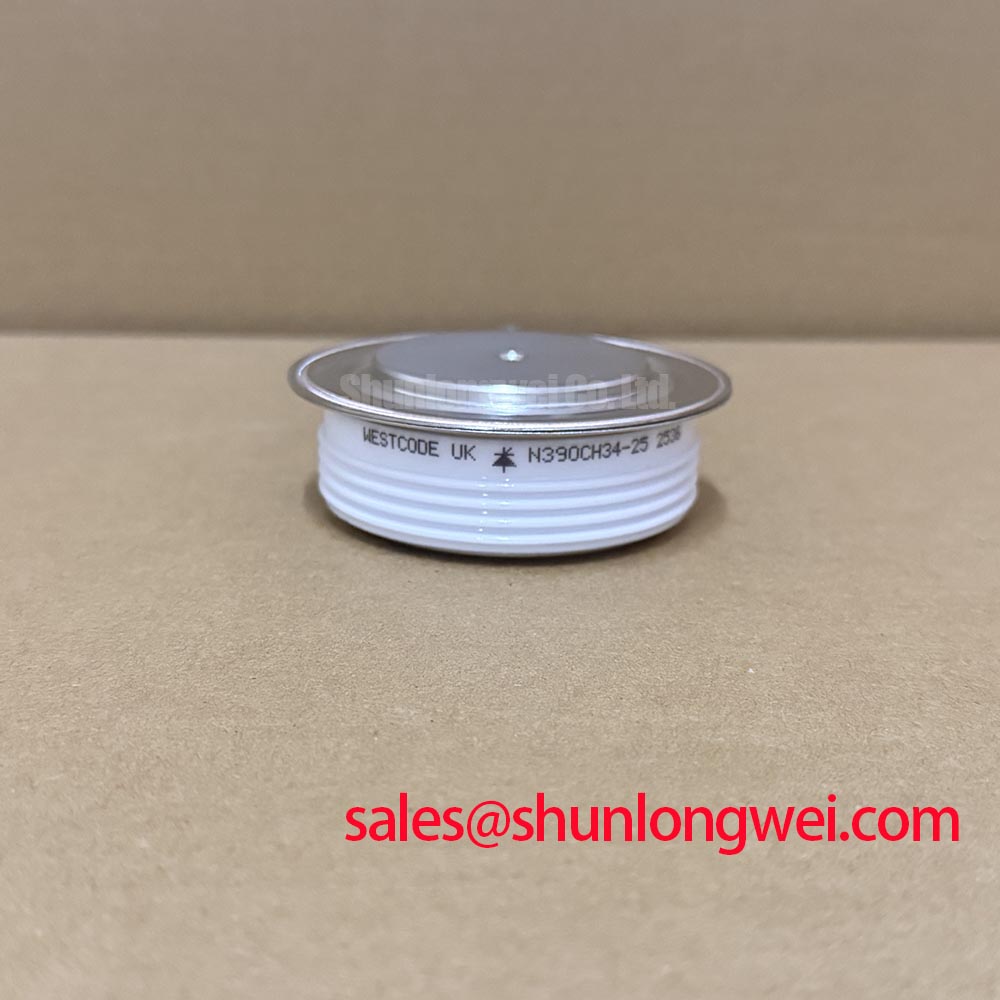
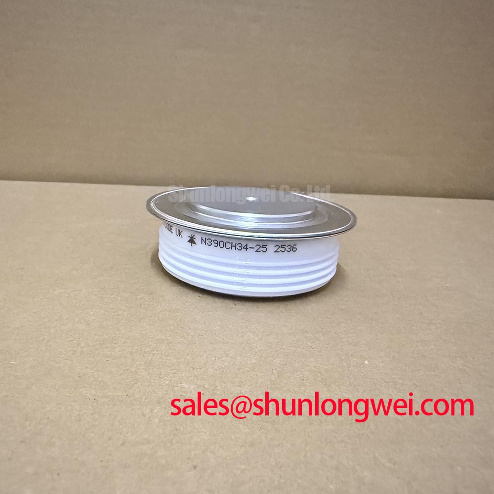
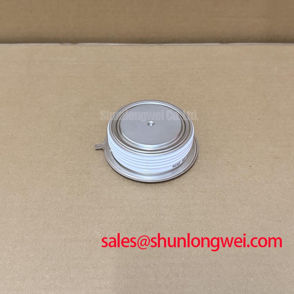
I separate a rectifier conduction fault from a firing-control fault by tracing where the N390CH34-25 sits in the power circuit. Its specified classification is a diode: a firing-angle command belongs to the controlled devices elsewhere in the converter, not to a gate terminal on this component. Identify the anode and cathode from the device drawing and equipment schematic rather than inferring polarity from its installed position.
Design Consideration: An AC-to-DC transfer assessment must distinguish an uncontrolled rectifier from a fully controlled or mixed bridge. Across a firing-angle sweep from 0° to 150°, average output voltage, conduction intervals, and reactive demand depend on bridge arrangement, current continuity, source impedance, and load conditions. A cosine-based expectation for one converter arrangement is not a universal diagnostic limit for another.
During an equipment-authorized test, compare the controller command with line synchronization, bridge output, and load-current waveforms. Delayed conduction can change displacement power factor; distorted input current also affects total power factor. Record these separately so a synchronization error or discontinuous load current is not mistaken for a defective capsule.
Engineering Recommendation: For a medium-frequency induction melting or hardening furnace repair, assess this component at its actual rectifier position rather than assuming suitability for the high-frequency inverter stage. When procurement compares the Westcode N390CH34-25 with another diode, including SKND 150F12, match electrical characteristics, electrode arrangement, cooling interfaces, and mounting requirements independently; that comparison does not establish a drop-in replacement.
N390CH34-25 Circuit Protection & Reliability: Evaluating Post-Surge Reverse-Voltage Blocking
After a fuse operation, identify the fault-current path and clearing sequence before considering another energization. With the circuit safely discharged and the component electrically isolated, compare forward and reverse meter responses using the same instrument setup. An unexpected reading supports further investigation, but parallel circuitry, instrument compliance, and temperature can affect the result; a handheld meter does not establish rated reverse-blocking capability.
Design Consideration: A sinusoidal 10 ms half-cycle surge assessment must use the manufacturer's applicable diode surge-current designation, commonly I_FSM, rather than automatically applying the thyristor notation I_TSM. The pulse duration, initial junction temperature, waveform, and reverse-voltage conditions belong together. A nonrepetitive surge rating must not become a repetitive operating allowance.
For the fuse coordination record, compare the fuse manufacturer's total clearing I²t and peak let-through current with the semiconductor's applicable withstand data under matching conditions. Include prospective fault current, circuit voltage, and the protective device's operating conditions. A fuse current rating alone cannot establish coordination, and a successfully cleared fault does not establish that the semiconductor remains serviceable.
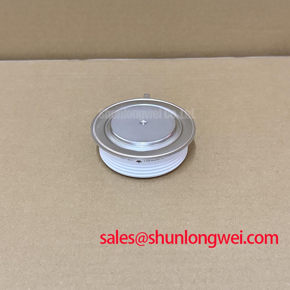
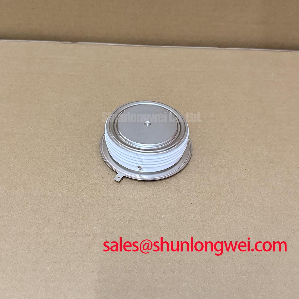
Engineering Recommendation: Before reverse voltage is reapplied, assess the preceding thermal load, cooling condition, and the applicable surge-test restrictions. Use the approved equipment procedure for blocking tests and recommissioning. On the mechanical side, distinguish capsule clamping force from fastener torque: the relationship depends on the clamp assembly, not simply the bolt diameter.
Field Alert: Never substitute a generic bolt-torque value for the press-pack assembly's specified clamping procedure.
Preventing Spurious Faults: Minimizing Commutation Voltage Spikes for N390CH34-25
Capture diode current and reverse voltage during commutation before attributing a transient trip to reverse recovery. Use appropriately rated probes, observe their operating limits, and minimize measurement-loop pickup. Correlating both waveforms helps distinguish a genuine switching transient from probe-induced ringing or a disturbance originating elsewhere in the bridge.
Design Consideration: Reverse-recovery peak current and recovery time are meaningful only alongside their test conditions, including forward current, current fall rate, junction temperature, and applied reverse voltage. Recovery time alone does not demonstrate soft recovery. Evaluate the current tail and associated voltage overshoot together rather than assigning an unsupported recovery characteristic to this model.
Reduce unnecessary commutation-loop inductance where the equipment layout permits, while preserving required clearances and service access. Any snubber alteration should follow measured transient behavior and system-level verification. The Ultimate IGBT Knowledge Base provides background for reviewing adjacent switching stages, but its transistor guidance does not establish diode ratings.
The Wolfspeed Silicon Carbide Schottky Diodes resource describes a different diode technology; its characteristics must not be transferred to the N390CH34-25. Close the commutation check by comparing measured peak reverse voltage, ringing, and component heating with the approved device limits and equipment acceptance criteria.