


Content last revised on September 25, 2026
Suppressing Pixel Jitter and Horizontal White Lines Near Variable Frequency Drives
When a display is installed beside a variable frequency motor drive, begin with the physical cable route rather than changing panel settings. Keep the display signal harness away from motor output conductors, braking resistor wiring, contactor coils, and high current DC link paths. If the existing equipment uses a shielded FFC, LVDS cable, or dedicated display harness, document how the shield is terminated at the original installation. A replacement cable with a different shield termination can change the common mode current path and may introduce intermittent pixel jitter, horizontal bands, or unstable image regions.
A 360 degree shield termination is a Design Consideration for reducing high frequency coupling when the enclosure and connector system support it. The final grounding method remains system dependent because chassis bonding, protective earth, cable length, connector construction, and drive cabinet layout all affect the result. Engineers should verify the shield connection with the equipment powered down first, then compare the display signal and supply rails during operating conditions using suitable measurement equipment.
Common mode ferrite suppression may also be evaluated as a Design Consideration when radiated or conducted interference is suspected. Ferrite selection should be based on the cable construction, frequency range, current level, and the effect on the intended signal. It should not be treated as a guaranteed correction for every white line or jitter symptom. A useful diagnostic comparison is to operate the display with the adjacent drive disabled, then repeat the test while observing the display supply, signal reference, and chassis potential. Changes in the symptom can help identify a coupling path, but they do not establish a single root cause without measurement.
The available product information does not specify an LED backlight life rating, an MTBF value, or a brightness decay curve for this model. Do not assign a 50,000 hour half brightness claim to the NL8048BC19-02C without a manufacturer data sheet or qualification document that states the test conditions. Backlight ageing depends on operating current, thermal conditions, brightness setting, duty cycle, enclosure temperature, and the characteristics of the installed driver. If long operating periods are required, the system owner should define an acceptance test that records luminance and uniformity over time.
💡 Pro Tip: Route the display differential pair as a controlled, balanced path and keep its reference and shield arrangement consistent from the controller board to the panel connector.
Controlled Differential Impedance Flex Routing for High Frequency Signal Integrity
The NL8048BC19-02C is identified as a TFT-LCD display module, but the supplied factory parameter set does not confirm whether the specific unit uses LVDS, TTL, or another panel interface. The integrator should verify the original panel documentation and connector drawing before selecting a transmitter board, cable, or timing controller. Do not assume that a mechanically compatible connector has the same pin assignment, data polarity, clock position, or power sequencing.
For an LVDS implementation, 100 ohm differential impedance is a common Design Consideration for the signal path. It is not an independently verified electrical specification for this model in the available information. The PCB stackup, flex construction, connector transition, cable geometry, and return path should be reviewed together. Uncontrolled routing can increase reflections and common mode conversion, particularly when the display cable passes through a metal frame or changes direction near a noisy power stage.
When commissioning a replacement panel, compare the known good and suspect signal paths with an oscilloscope that is suitable for the interface. Observe the differential clock and data behaviour at the receiving end, not only at the transmitter. Intermittent split screen images, missing columns, unstable colours, and horizontal artefacts may be associated with timing mismatch, poor signal integrity, incorrect data mapping, grounding differences, or an unsuitable timing controller. The measurement should therefore be correlated with the original equipment documentation rather than interpreted as proof of one specific failure mechanism.
JEIDA and VESA mapping must be treated as separate compatibility checks. A panel can have the correct resolution and connector style while using a different colour bit order or lane arrangement. Confirm the mapping of red, green, and blue data bits, the pixel clock relationship, lane polarity, and any required signal inversion. The timing controller should also be checked for horizontal and vertical timing values specified for the original display. The available information does not provide those values for the NL8048BC19-02C.
Power sequencing requires the same discipline. The supplied record does not confirm whether the logic rail is 3.3 volts or 5.0 volts, and it does not provide a permitted rise time, enable order, or reset delay. The system integrator should verify the required supply voltage from the original panel documentation. Apply power only after confirming the connector pinout and measuring the rail with the panel disconnected. After connection, observe the supply during startup and shutdown to identify overshoot, delayed enable behaviour, or interaction between the timing controller and backlight circuit.
Optical performance should be validated under the actual installation lighting. The available factory data does not state a contrast ratio, luminance value, anti glare treatment, or anti reflective coating for this model. Direct sunlight can reduce perceived contrast even when the electronic image is correct. A surgical navigation or ultrasound terminal may require a controlled assessment of black level, white level, viewing angle, reflection, and image detail at the intended enclosure angle. These are system acceptance criteria unless the panel manufacturer provides measured values under defined conditions.
Chassis Fastener Loading and Mechanical Alignment
Before fitting the NL8048BC19-02C into an existing bezel, compare the panel outline, active area position, connector clearance, cable exit direction, and mounting hole pattern with the original assembly. The available official parameter record does not include external dimensions, mounting hole coordinates, bezel envelope tolerances, or a fastener torque specification. These values must be obtained from the original drawing or measured from the removed panel and chassis.
Mechanical stress can affect image uniformity even when no visible glass damage is present. A bezel that contacts the active area, a bracket that is not flat, or fasteners tightened unevenly may introduce local pressure and produce bright or dark regions. Such optical mura should be investigated by loosening the mechanical constraint under controlled service conditions, checking the frame alignment, and comparing the image before and after installation. This procedure can reveal a mechanical contribution, but it should not be used to assign a fixed torque value to this model without an approved mechanical specification.
Cross pattern tightening is a general Design Consideration for distributing clamping load across a rectangular display assembly. The actual fastener type, thread engagement, bracket material, washer arrangement, and manufacturer requirements determine the permissible torque. Avoid using a torque value copied from another NEC display or from a different chassis. Any specified M3 torque range must come from the equipment drawing or an approved assembly procedure.
Touchscreen compatibility also requires separate verification. The supplied data identifies the product as an industrial grade LCD/HMI panel but does not confirm a resistive touch layer, projected capacitive sensor, glove operation, water rejection, controller interface, or cover glass treatment. If the target equipment uses industrial touch input, the replacement assembly should be checked for touch controller communication, active area alignment, bezel clearance, grounding, and response under gloves or moisture. These characteristics cannot be inferred from the TFT-LCD designation alone.
Temperature testing should include both electrical timing and mechanical fit. The original equipment designer should verify display startup, grey scale transitions, image stability, backlight behaviour, and connector retention across the intended operating window. TTL or LVDS clock margin and data hold time are determined by the panel interface specification and timing controller combination. They should be measured or calculated from documented limits rather than estimated from the model number.
For optical inspection, use repeatable test images containing black, white, grey, and fine line patterns. Check for stuck pixels, vertical bands, horizontal lines, uneven luminance, colour imbalance, and image retention after the panel reaches a stable operating condition. Record whether an artefact follows the panel, remains with the controller, or changes when the cable is moved within safe service limits. This separation helps distinguish display assembly behaviour from upstream video electronics without claiming a single cause prematurely.
Backlight Evaluation and Replacement Integration Pathways
The available factory information does not confirm whether the NL8048BC19-02C uses an LED or CCFL backlight, nor does it provide a backlight current, ignition voltage, dimming method, luminance rating, or service life value. The integrator should verify the required backlight supply and control method from the original panel documentation. A constant current LED driver must not be connected to a panel until the backlight configuration and connector assignment have been confirmed.
If the original equipment uses a high voltage fluorescent backlight, the service procedure must account for the inverter, insulation, connector spacing, and discharge conditions specified by the equipment manufacturer. If the assembly uses an LED backlight, the driver should be evaluated for current regulation, enable logic, fault response, dimming compatibility, and conducted noise. An LED retrofit is not automatically electrically compatible simply because the display envelope appears similar.
PWM dimming behaviour should be checked at the system level. The available product record does not verify a 1000 to 1 dimming ratio, acoustic performance, or a guaranteed half brightness life. Engineers should compare visible flicker, camera interaction, low brightness uniformity, and thermal behaviour at the intended operating settings. Medical imaging and diagnostic equipment may impose additional system requirements for brightness stability and image consistency, which must be established by the equipment manufacturer.
The NEC NL8048BC19-02C may be compared with another display during sourcing, but replacement decisions should be based on verified electrical and mechanical compatibility rather than nominal appearance. The NL10276BC16-06 can be reviewed as a separate display option for comparison, subject to its own documentation and interface checks. It should not be treated as a drop in substitute without confirming resolution, connector definition, timing, dimensions, backlight control, and mounting conditions.
For a broader display power and control review, engineers may also examine the NL10276BC30-24D as a related display solution. Any relationship between the two products must be established from the equipment schematic and manufacturer documentation. The Industrial Display and HMI Solutions resource provides additional context for evaluating enclosure integration, environmental conditions, and display system design without replacing the model specific data sheet.
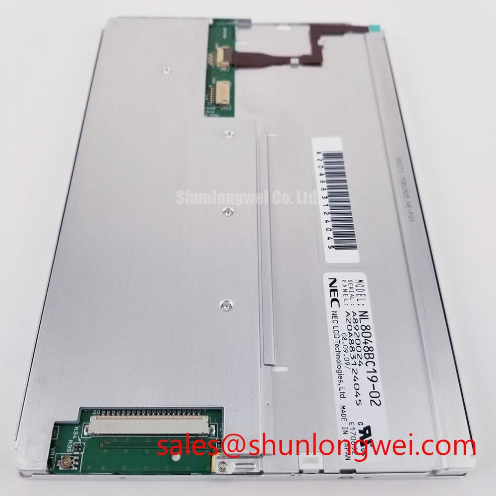
For procurement and repair records, retain the complete model marking, connector photographs, removed panel measurements, controller board identification, backlight harness details, and the equipment revision. The confirmed product identity is NEC NL8048BC19-02C, classified as an Industrial Grade LCD/HMI Panel and supplied in a TFT-LCD Display Module format. Unconfirmed values should remain open engineering checks until the original panel documentation or an authorized technical drawing provides the required limits.
