




Content last revised on October 27, 2026
P588A4108 Circuit Protection & Reliability: Auxiliary Emitter Pinout Cold-Check
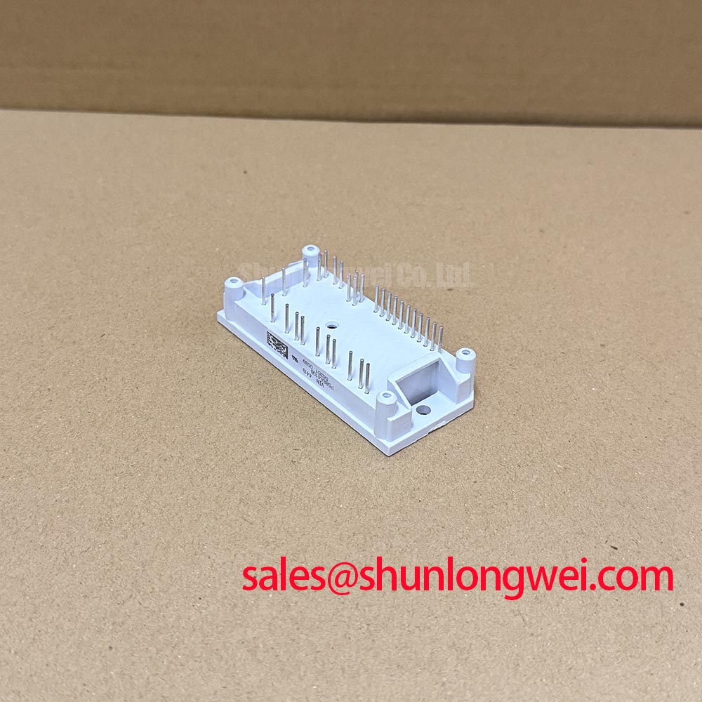
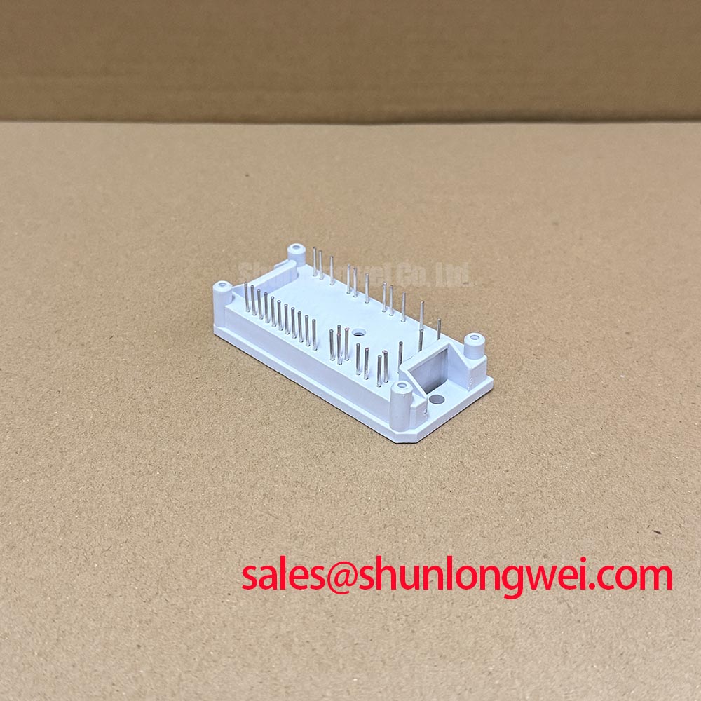
I first trace the driver return against the terminal drawing, rather than identifying an emitter connection by its position on the housing. For P588A4108, the terminal assignment must establish whether a separate auxiliary emitter connection exists before any Kelvin-return troubleshooting applies. A low resistance between two terminals does not establish their intended circuit roles; the surrounding board can introduce parallel paths through protection components and driver circuitry.
Design Consideration: Where the documented interface provides a separate emitter return, distinguish it from the main load-current connection throughout the driver loop. Shared emitter inductance can produce a voltage disturbance during rapid current changes, altering the gate voltage experienced by the switch. Inspect the return route at connectors, solder joints and board transitions. A dedicated terminal provides little benefit if the external layout immediately merges its return into a high-current path.
Before an unpowered check, disconnect power, discharge stored energy and verify the circuit is de-energized according to the equipment service procedure. Isolate the relevant driver connections sufficiently to distinguish module behavior from board loading. Compare equivalent switch positions using the same meter polarity and measurement conditions. Unexpected asymmetry warrants further isolation, not an immediate verdict on the module. Check connector retention and terminal damage before interpreting a fluctuating reading as an electrical defect.
For powered investigation, use appropriately rated differential instrumentation to observe gate voltage relative to its intended local emitter reference. Keep the measurement loop compact and distinguish probe pickup from actual gate disturbance. The Evolution of Negative Off-Bias Gate Drive Circuits provides background for assessing off-state control; negative bias is a system-dependent measure, not an established P588A4108 requirement. Driver limits, switching behavior and measured gate excursions should determine its suitability.
P588A4108 Operational Boundaries: Evaluating Thermal Grease Pump-Out
Inspect the heatsink contact surface and module mounting face before disturbing the old interface material. Record uneven residue, displaced compound and localized contact marks because they can guide the next mechanical inspection. Do not assume a copper baseplate, a specified convex profile or a particular internal substrate construction from the package-family reference alone. Establish the applicable mounting arrangement from the mechanical drawing.
Design Consideration: Assess heatsink flatness, surface cleanliness and mounting-hole alignment together. A module that rocks before fastening needs investigation rather than additional clamping force. Where the mounting instructions specify multiple fasteners, progressive tightening in the prescribed sequence can help distribute pressure. The final torque, hardware and interface-material application must follow the approved assembly instructions rather than a generic value inferred from screw diameter.
Field Alert: Do not pull a misaligned module flat with its mounting screws; correct the seating condition before applying the specified tightening torque.
Thermal-interface pump-out is an assembly and operating-condition concern, not a defect that can be declared eliminated by a nominal grease thickness. Review compound compatibility, contact pressure and evidence of displacement during servicing. Use the interface material’s application method to control coverage without treating an arbitrary film thickness as a P588A4108 specification. Evaluate the resulting case-temperature distribution under comparable loading and cooling conditions.
Check high-side driver supply integrity separately from the thermal joint. As an Engineering Recommendation, where the host driver uses a bootstrap supply, assess capacitor charge demand from gate charge, driver quiescent consumption, leakage and the longest interval between recharge opportunities. Include capacitance tolerance and voltage-dependent capacitance loss. Observe the supply relative to its floating return during the relevant switching sequence; select capacitance and recharge provisions from the driver’s permitted voltage droop and undervoltage behavior, not from package size.
Assembly Integrity & Layout Architecture: Assessing Type-2 Coordination for P588A4108 IGBT Module Protection
Compare the protection schematic with the installed fuse, DC-link arrangement and driver fault path before approving a replacement assembly. A semiconductor fuse and a gate-driver shutdown circuit act on different timescales and address different fault conditions. Their presence alone does not establish Type-2 coordination or guarantee that a module enclosure will remain intact during a short circuit.
Design Consideration: Assess fuse total clearing I²t, interrupting capability and operating voltage against the prospective fault current and the protected circuit’s documented withstand characteristics. An IGBT’s short-circuit safe operating area cannot automatically be reduced to a fuse-style I²t limit. Type-2 coordination requires applicable assembly-level evidence; it should not be assigned to P588A4108 merely because a high-speed fuse appears in the bill of materials.
For driver protection, examine desaturation detection, fault blanking, shutdown propagation and the discharge path as a connected sequence. Desaturation monitoring observes collector-emitter behavior during conduction; it is not simply a static saturation-voltage check. If soft shutdown is implemented, its behavior must balance fault-current interruption against turn-off overvoltage within the device’s documented operating boundaries. Inspect the sensing connections and fault latch before changing thresholds.
Minimize the commutation-loop area where the assembly permits, and preserve the intended laminated-busbar arrangement. Stray inductance can increase turn-off voltage stress, so assess changes to terminal adapters, capacitor placement and busbar spacing against measured switching behavior. Required clearance and creepage depend on the equipment’s insulation coordination, working voltage and installation conditions, rather than a universal module-layout spacing.
For procurement comparison, treat SKKR300/0.2-BVR as a separate component requiring independent evaluation, not an asserted substitute. Compare circuit function, terminal arrangement, electrical limits, mounting geometry and protection requirements before considering interchangeability. Commercial string inverters and micro-grid energy-storage converters are potential compatibility-assessment contexts, not verified P588A4108 installations.
Benchtop Waveform Tuning: Assessing Stress via Transient Thermal Impedance on P588A4108
Capture the load-pulse duration, repetition pattern and case-temperature reference before estimating peak junction temperature. A short overload and a sustained load can produce different internal temperature rises even when their average power is similar. Use switching and conduction losses representative of the actual gate drive, current and operating temperature rather than relying on a single headline current rating.
Engineering Calculation: For a constant-power pulse under the assumptions of the applicable junction-to-case thermal model, the junction-temperature rise is estimated as ΔTj = P × Zth(j-c)(t). The transient thermal impedance must correspond to the relevant thermal path and pulse duration. Repetitive or varying losses require thermal superposition or a validated time-domain model that accounts for residual heat between pulses.
A multi-RC thermal network can represent that time dependence when its coefficients come from the applicable manufacturer model. Keep the model’s reference node consistent with the measured case temperature, and respect distinctions between Foster and Cauer representations when extending the cooling network. Do not assign invented thermal resistances or time constants to P588A4108. Include sensor placement and thermal lag when comparing the model with bench observations.
During waveform tuning, change one control variable at a time and record collector-emitter overshoot, gate excursions and switching loss together. Reducing one stress can increase another, especially when slower transitions increase dissipated energy. If the host assembly uses parallel modules, the Infineon IGBT Paralleling Application Note provides general background on current sharing; it does not establish P588A4108-specific limits.
For equipment with alternating charge and discharge operation, evaluate both load directions and the transitions between them. Compare predicted peak junction temperature and temperature swing across the duty sequence, then validate the thermal response with the intended cooling arrangement. Use that evidence to assess operating adjustments without assigning an unsupported service-life extension or treating a cool heatsink as proof of adequate junction-temperature margin.