

Content last revised on October 8, 2026
PC1008 Snubber and Terminal Checks
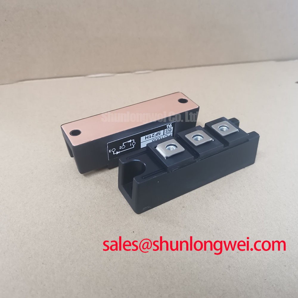
With the power isolated, compare the terminal markings on the installed module with the equipment schematic before disconnecting its conductors. For PC1008 from Nihon Inter (NIEC), the supplied product specification identifies a 100.0 A current rating and an isolated power module package (Official Specification). It does not provide a numerical voltage rating or confirm the internal thyristor and diode connections. Those details must be checked against the original module documentation before an installation or replacement decision.
An RC snubber should be assessed against the switching event it is intended to control, not selected from the module current rating alone. As a Design Consideration, an engineer evaluating PC1008 should inspect the existing snubber connections, then measure voltage transients across the relevant power terminals under controlled operating conditions. The required resistance and capacitance depend on the circuit topology, stray inductance and measured waveform. If the equipment uses a series saturable reactor, its position and condition should also be checked against the original schematic rather than assumed from the module designation.
Before reconnection, record conductor positions and inspect contact faces for damage or uneven seating. The available specification does not state terminal assignments, mounting torque or a fuse coordination value. Match the terminal diagram and specified tightening procedure to the original documentation; compare the selected fuse’s clearing energy with the device’s published surge and I²t limits only when those limits are available. A PGH50N16 listing can be consulted during a separate replacement assessment, but its electrical ratings, internal circuit, package and terminal layout require independent comparison before it is treated as interchangeable.
AC Input Surge Protection Around PC1008
For a power stage supplied from an industrial AC input, trace the protection path from the incoming conductors to the module before changing MOVs or snubber parts. As a Design Consideration, the protective components should be assessed against the installation’s supply voltage, anticipated surge exposure and coordination with upstream protection. Measure the voltage that reaches the relevant PC1008 terminals during system testing; a snubber at the module and surge protection at the input address different parts of that path.
IEC 61000-4-5 describes surge immunity testing at the equipment level; it does not establish a surge rating for PC1008. Where a design includes a separate front-end or auxiliary power stage, the PK55FG120 listing is relevant to a topology review, not proof of compatibility with this module. For diode-related device terminology and test context, consult IEC 60747-2. Protection values and acceptance criteria remain decisions for the measured assembly and its documented requirements.
Thermal Contact and Operating Boundaries
Inspect the heatsink contact area when removing PC1008, noting uneven compound transfer, loose mounting hardware or debris that could impair contact. The supplied product specification identifies an isolated package but gives no baseplate material, junction-to-case thermal resistance or transient thermal impedance value. It therefore cannot support a numerical junction-temperature estimate on its own. Obtain the applicable thermal data and mounting instructions before evaluating continuous current or repetitive heating in the equipment.
As a Design Consideration, engineers assessing a medium-frequency induction melting or hardening furnace should measure the module’s operating conditions across the actual duty cycle, including start-up and high-load periods. Transient thermal impedance matters when a current pulse heats the junction faster than the heatsink reaches steady state. Check heatsink temperature, current waveform and cooling performance together, then evaluate junction-temperature margin using verified device data. 💡 Pro Tip: Keep the mating surfaces clean and verify the specified mounting procedure before using temperature readings to judge the module’s thermal margin.
Commutation Layout and Reverse Recovery Assessment
Review the physical current path between PC1008, its connected conductors and any commutating devices. As a Design Consideration, reducing unnecessary loop area can help limit inductive overshoot, but the result should be confirmed by measuring the switching waveform at the installed terminals. If a diode in the documented circuit undergoes reverse recovery, peak recovery current and recovery time may affect switching loss and conducted noise. Neither value is supplied for PC1008, so they should not be assigned to this model without its original device data.
The Mitsubishi Electric diode module lineup illustrates why circuit configuration and published device characteristics must be compared when reviewing power-module options; it does not establish a PC1008 specification. For broader discussion of modular power-stage layout, see The Race for Efficiency. For this installation, use the original terminal diagram and measured commutation waveform to assess voltage stress before approving the assembly.