Content last revised on September 19, 2026
Benchtop Waveform Tuning: Mitigating Stress in Converter Applications Using PD2504
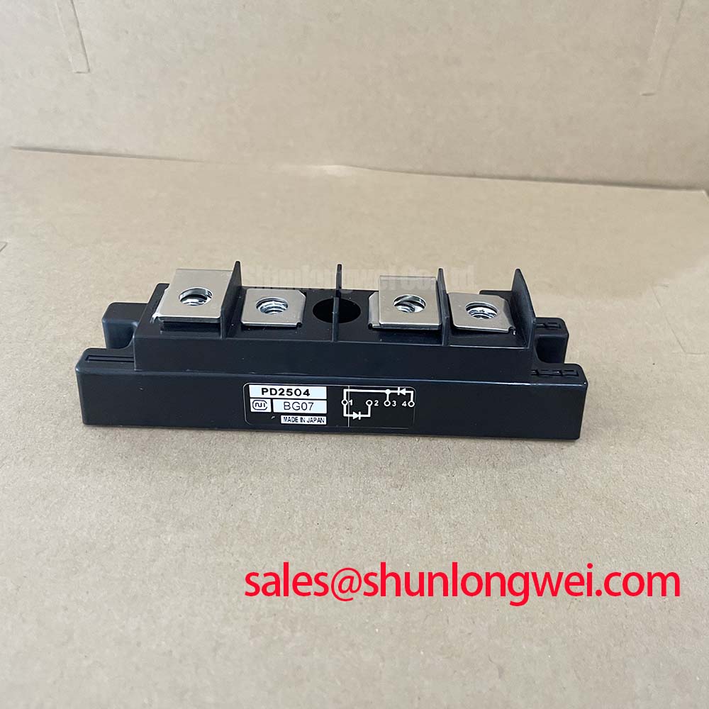
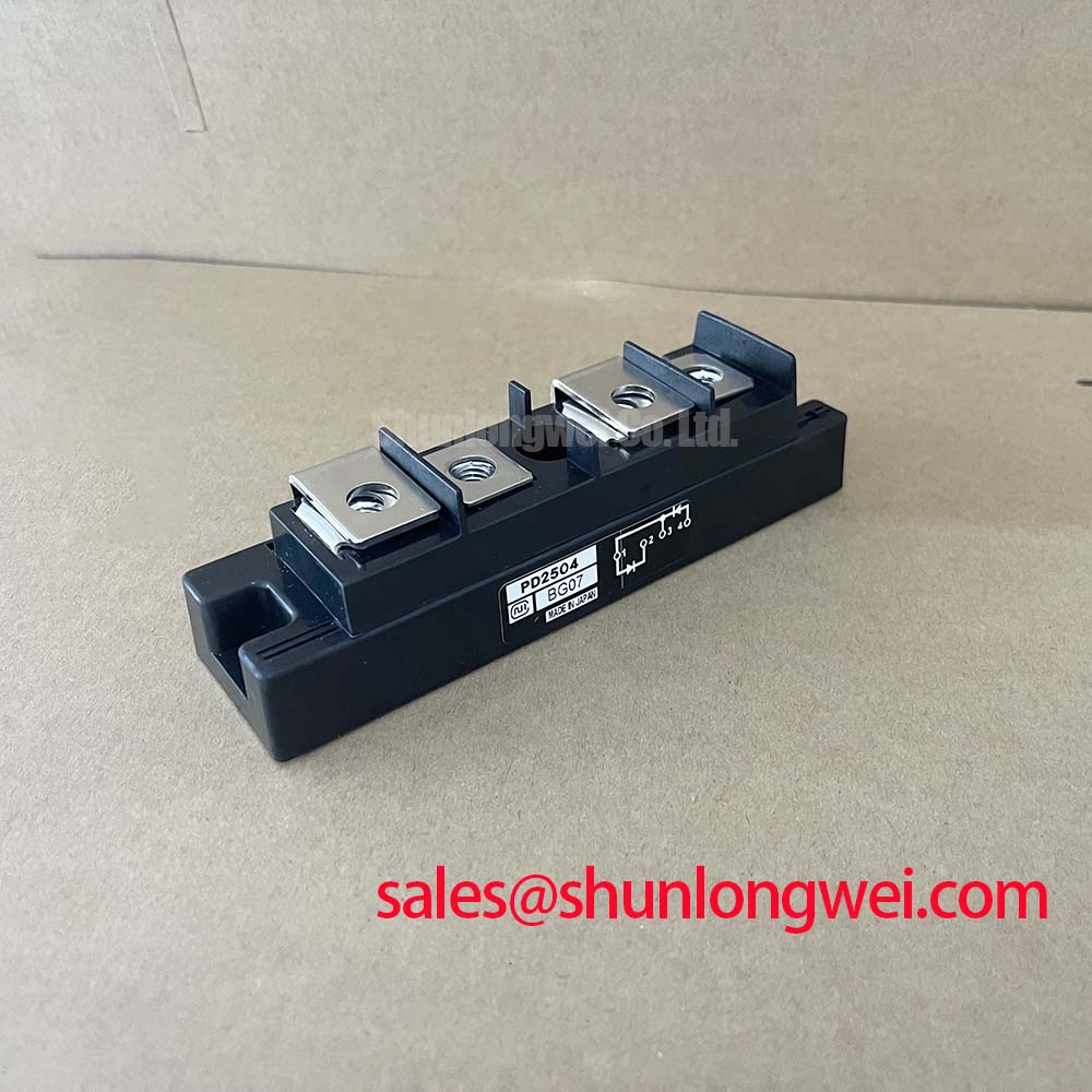
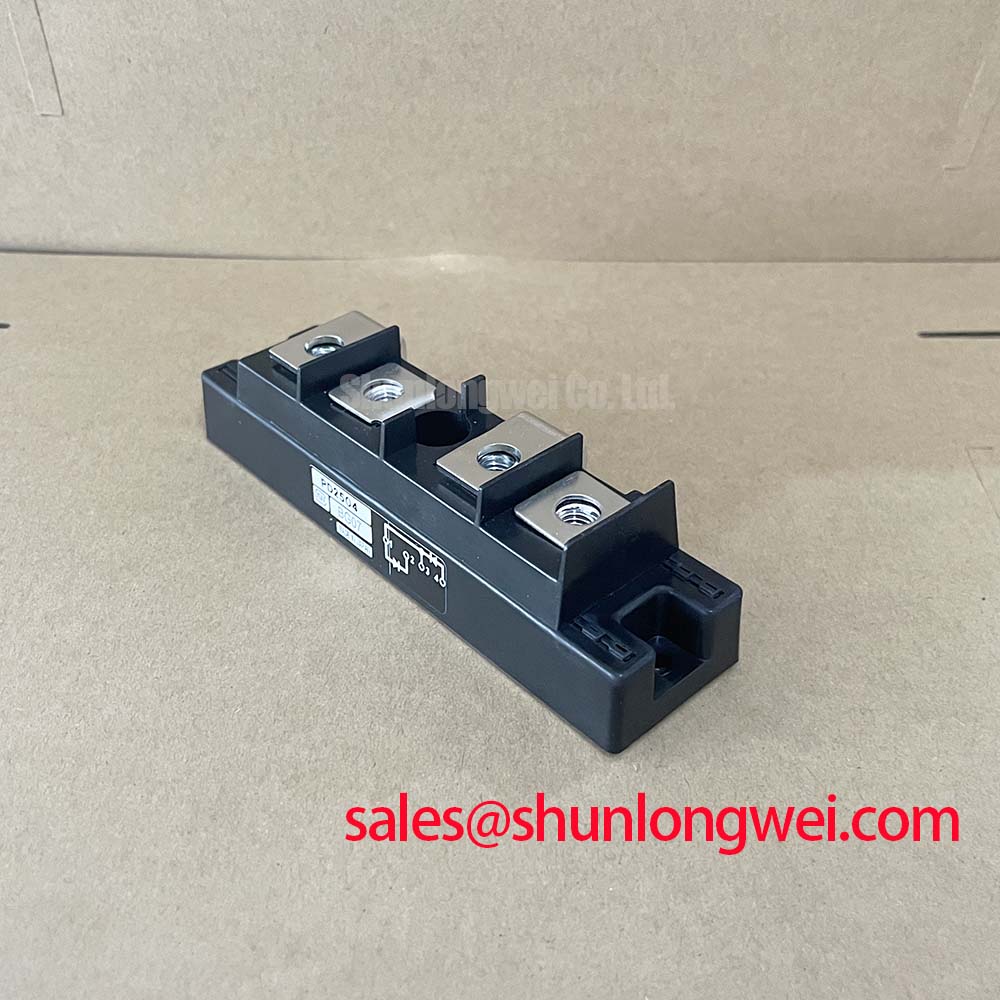
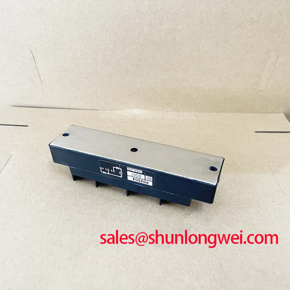
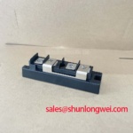
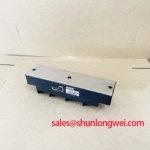
Before reconnecting a removed unit, verify the nameplate against the converter documentation and confirm that the installed device is a PD2504 with a 400 V voltage rating, 25 A current rating, and Isolated Power Module housing. These are official datasheet specifications for the SanRex Sansha Electric module. The external circuit drawing and original equipment service documentation remain necessary to confirm terminal allocation and internal device arrangement.
In phase-controlled equipment, an isolated firing circuit must deliver a clean, repeatable trigger signal without allowing the power-stage transient environment to disturb the control electronics. A pulse transformer is commonly evaluated where galvanic separation between the controller and an associated thyristor gate circuit is required. The PD2504 itself is a diode module and does not receive a gate-firing signal. Winding polarity, pulse duration, reset behavior, and isolation performance must therefore be assessed for the associated controlled devices at the system level rather than assumed from the PD2504 rating alone.
A trigger pulse with a slow or inconsistent rising edge can create irregular turn-on behavior in an associated controlled device between firing events. This can show up as unequal current sharing in parallel paths, abnormal acoustic noise from the power transformer, or unstable output during low-load operation. Design Consideration: observe gate-related waveforms with appropriately isolated test equipment and compare repeated firing pulses against the known control timing. Do not infer a required gate-current rise rate, holding current, or pulse width for associated controlled devices from the PD2504 voltage and current ratings because those values are not stated in the available product specifications.
Multi-pulse firing can be considered by the system designer when load conditions make a single trigger event unreliable. The test objective is practical: confirm that every intended firing event occurs at the commanded phase position and that no unintended retriggering is present in the associated controlled devices. Check the gate return path, pulse-transformer secondary connections, control-board reference points, and connector retention before changing firing logic.
The protection chain also deserves attention during commissioning. Fuse selection requires coordination with the complete converter fault study, including available fault current, conductor impedance, and the protection-device time-current characteristics. No PD2504-specific fuse I²t value is provided here, so a fuse rating must not be assigned from the module’s 25 A nominal current alone. The maintenance team should retain the original fuse documentation and investigate any replacement that differs in semiconductor protection class or interrupting capability.
For broader circuit-level checks involving gate-drive isolation for associated controlled devices, commutation paths, and thermal management, the IGBT Design & Integration reference provides useful test-planning context. Its principles should be applied only after the PD2504 topology and the associated controlled-device topology have been verified from the equipment documentation.
Field Diagnostics & Commissioning: Baseplate Thermal Resistance in PD2504 Topologies
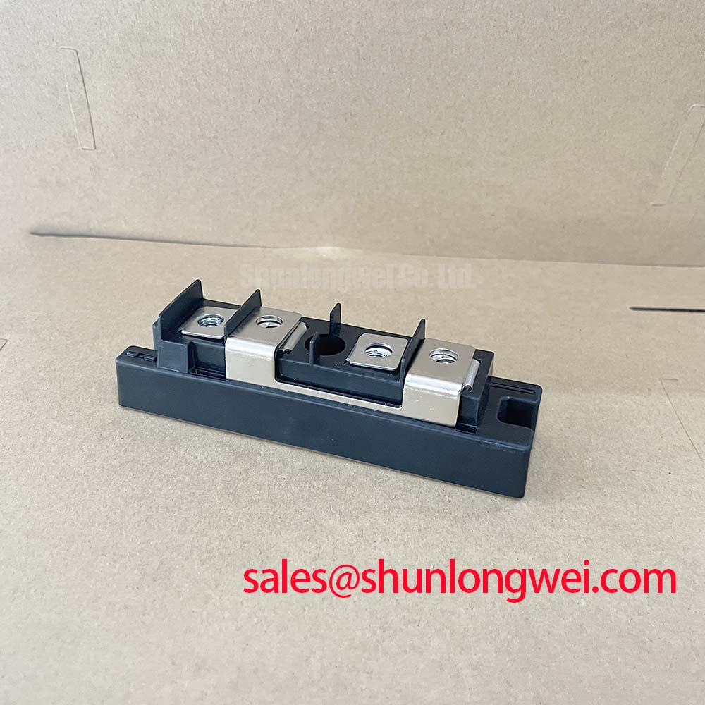
The PD2504 uses an Isolated Power Module package, but the available official information does not specify junction-to-case thermal resistance, allowable mounting torque, baseplate dimensions, or screw size. These details should be confirmed from the original SanRex documentation or the equipment manufacturer’s assembly record before the module is installed on a heatsink.
Field diagnosis begins with the mechanical interface rather than a calculated thermal-resistance value. With power isolated and stored energy discharged according to site procedures, inspect the heatsink plane for corrosion, debris, raised burrs, old compound residue, and evidence that the module has previously been distorted by uneven clamping. A clean, flat mating surface and evenly distributed contact pressure are Design Considerations because they support predictable heat flow from the module case into the cooling assembly.
Apply thermal interface material only as specified by the equipment service procedure. The aim is continuous contact without trapped debris or excessive material that can interfere with seating. Tighten mounting hardware in a balanced sequence using the torque specified for the actual package and fastener arrangement. Terminal connections should also be checked for discoloration, looseness, conductor-strand damage, and evidence of heat cycling. A loose terminal can add resistance and produce localized heating that is separate from semiconductor junction behavior.
⚠️ Maintenance Note: Periodically monitor terminal and heatsink contact temperature during normal duty, then clean the cooling path and inspect mounting hardware according to the equipment maintenance schedule. Retorque fasteners only when the equipment procedure specifies it.
After reassembly, temperature behavior should be assessed under controlled operating conditions. A rising heatsink temperature may be associated with blocked airflow, degraded thermal interface material, reduced coolant circulation, increased process duty, poor electrical contact, or changes in commutation behavior. It should not be attributed to one cause without measurement. Compare airflow or coolant performance, power-stage current, terminal temperature, and the waveform condition against a known stable operating state.
Moisture control also matters in cabinet-level maintenance. Condensation on busbars, connector insulation, or control boards can alter leakage paths and contribute to unstable operation. Keep the enclosure sealed as intended, inspect cable entries, and return the machine to service only after moisture-related concerns have been addressed. Information on the manufacturer’s power semiconductor portfolio is available through SanRex Sansha Electric Power Semiconductors and ICs.
Field Diagnostics & Commissioning: Minimizing Commutation Turn-Off Voltage Stress in PD2504 Topologies
The stated 400 V rating defines an important official electrical boundary, but it does not independently describe the actual switching or commutation peak in a specific converter. During troubleshooting, verify the DC-bus condition, wiring layout, snubber condition where fitted, and device waveform behavior together. Stray inductance in the current loop can contribute to transient voltage during current transfer, especially when conductors, busbars, or capacitor connections have been altered during repair.
Where a PD2504 circuit includes diode commutation, reverse-recovery behavior can influence transient current, turn-off voltage stress, ringing, and conducted or radiated noise. The available data does not provide PD2504-specific reverse-recovery peak-current or recovery-time values. Engineers should therefore measure the installed assembly with suitable bandwidth, probe arrangement, and safe isolation practices rather than applying generic diode-recovery figures to this module.
Design Consideration: minimize unnecessary loop area in the commutation path to reduce inductive overshoot, then verify voltage peaks against the actual DC link and device ratings during controlled switching tests. This is a system-verification task. It depends on busbar construction, snubber placement, cable routing, timing of associated controlled devices, load current, and the characteristics of connected devices.
Inspect capacitors and suppression components as part of the same diagnostic pass. A change in capacitor condition, connection resistance, or snubber wiring can alter waveform damping and cause repeated stress even when the PD2504 itself appears electrically intact during static checks. Oscilloscope captures should be taken only by personnel using measurement methods appropriate to the voltage environment.
For service teams comparing module families, Shindengen Power Semiconductor Modules and Diodes offers a useful external reference for reviewing how module category, terminal layout, and published electrical data must be considered together. It is not evidence of direct interchangeability with PD2504.
Assembly Integrity & Layout Architecture: Evaluating Dynamic Firing Delay Angle Adjustment in PD2504 Converter Applications
In a phase-controlled AC-to-DC stage, firing delay angle changes the interval during which the converter transfers energy from the AC source to the load. A control range from zero through high delay angles can be present in industrial rectifier systems, but the actual permitted range, output characteristic, transformer loading, and reactive-power behavior are determined by the converter topology and its control design. They are not official standalone specifications of the PD2504 module.
For medium-frequency induction melting and hardening furnace power supplies, technicians may encounter PD2504 units in rectifier sections alongside controlled devices, subject to application-specific verification. Before adjusting firing delay, establish whether the reported problem is process-related, source-voltage-related, control-related, thermal-related, or caused by the power circuit. Record commanded angle, measured output, supply waveform, current balance, and cooling condition. This avoids changing a timing parameter when the actual fault lies in a loose connection or impaired cooling path.
As the firing angle is delayed, source-current waveform shape and reactive-power demand can change. Harmonic behavior is therefore a system concern involving transformer impedance, line-reactor arrangements, input filtering, load conditions, and the converter’s programmed control strategy. Engineering Recommendation: retain the original control limits unless a qualified system engineer validates revised settings with measured source current and output performance.
When a replacement evaluation is necessary, the PD25016A can be reviewed as a related SanRex module reference. Mechanical fit, internal circuit topology, terminal designation, voltage class, current capability, diode characteristics, cooling interface, and protection coordination must all be confirmed against the original PD2504 installation before any substitution decision is made.
After commissioning, document the installed module marking, terminal connection orientation, heatsink service condition, control settings, and baseline waveforms. This record gives the next maintenance intervention a factual comparison point and helps isolate changes introduced by process loading, environmental conditions, or service work.