


Content last revised on March 8, 2026
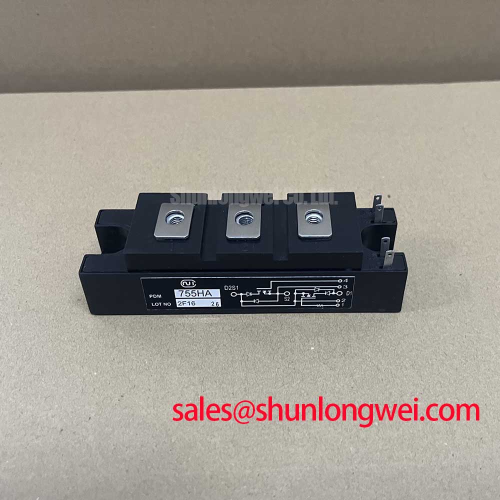
PDM755HA Kyocera 500V 75A Fast Recovery Diode Module
The PDM755HA, manufactured by Kyocera (formerly Nihon Inter Electronics), is a high-performance Fast Recovery Diode (FRD) Module designed for high-frequency power conversion where switching losses and electromagnetic interference must be minimized. Featuring a dual-diode configuration in a series connection, it serves as a critical rectification stage for industrial power systems. For engineers prioritizing thermal efficiency and noise suppression, this 500V 75A module provides a stable, isolated solution for demanding switching environments.
Core Specifications: 500V | 75A | trr ≤ 200ns
Key Engineering Benefits:
- Reduces switching stress in high-frequency converters through optimized soft recovery characteristics.
- Simplifies mechanical integration with an isolated mounting base, allowing multiple modules on a single heatsink.
What is the primary benefit of the PDM755HA soft recovery feature? It significantly reduces high-frequency noise and voltage spikes during diode turn-off, protecting adjacent sensitive components. For high-frequency SMPS designs requiring a balance of speed and ruggedness, the PDM755HA stands as a benchmark for reliable rectification.
Key Parameter Overview
Decoding the Specs for Enhanced Switching Reliability
The technical performance of the PDM755HA is defined by its ability to handle rapid transitions without excessive power dissipation. The following parameters represent the operational boundaries and thermal characteristics essential for system-level calculations.
| Parameter Group | Technical Specification | Value / Rating |
|---|---|---|
| Voltage Ratings | Repetitive Peak Reverse Voltage (VRRM) | 500V |
| Current Handling | Average Rectified Forward Current (IF(AV)) | 75A (Per Arm) |
| Switching Speed | Reverse Recovery Time (trr) | 150ns - 200ns (Typical) |
| Thermal Dynamics | Thermal Resistance Junction to Case (Rth(j-c)) | 0.45 °C/W |
| Isolation | Isolation Voltage (Visol) | 2000V AC (1 Minute) |
| Forward Voltage | Peak Forward Voltage (VFM) | 1.50V (at 75A) |
Download the PDM755HA datasheet for detailed specifications and performance curves.
Application Scenarios & Value
Achieving System-Level Benefits in High-Frequency Power Conversion
The PDM755HA is specifically engineered for applications where the "Reverse Recovery" phase of a diode can be a bottleneck for efficiency. In a high-speed switching environment, a diode is like a mechanical check-valve; if the valve closes too slowly or with a "bang," it creates water hammer—or in electronics, a voltage spike. The soft recovery characteristic of this module ensures the "valve" closes smoothly, preventing damage to the primary switching transistors.
In Switching Mode Power Supplies (SMPS) and Uninterruptible Power Supplies (UPS), the PDM755HA acts as the output rectifier or freewheeling diode. Its 500V rating makes it ideal for 200-240V AC input systems where the DC bus typically sits between 300V and 400V. By maintaining a low trr, the module minimizes the "shoot-through" current seen by the primary IGBT or MOSFET, directly extending the lifespan of the entire power stage. This reliability is vital for high-efficiency power systems utilized in industrial automation.
Engineers designing high-power welding machines or induction heating equipment often face the challenge of managing parasitic inductance. The PDM755HA helps mitigate these challenges. For systems requiring higher voltage handling, the related SKM75GB128D offers a Vces of 1200V, though it serves a different functional role as a full IGBT module. When compared to the BSM75GD120DN2, the PDM755HA provides a specialized fast-recovery rectification path that is often used in conjunction with such modules to manage inductive flyback.
Technical Deep Dive
A Closer Look at Soft Recovery and Thermal Management
The "Softness" of the recovery in the PDM755HA is a deliberate design choice. In many ultra-fast diodes, the current snaps to zero instantly, which excites parasitic oscillations (ringing). The PDM755HA uses a controlled carrier lifetime within the silicon to allow the current to decay in a more linear fashion. This acts like a shock absorber for the circuit, reducing the need for heavy and expensive Snubber Circuits, which can otherwise increase the total bill of materials (BOM).
Thermal management is the second pillar of this module's reliability. With an Rth(j-c) of 0.45 °C/W, the module can effectively transfer heat from the silicon junction to the baseplate. Think of this thermal resistance as the diameter of a drainage pipe; a lower value allows more "heat flow" to exit the system without causing a backup (overheating). This is critical for preventing thermal runaway in high-ambient environments such as motor drive cabinets. Proper understanding of failure analysis and overtemperature prevention is essential when deploying these modules in 24/7 manufacturing cycles.
Frequently Asked Questions
How does the 150ns trr of the PDM755HA impact the choice of switching frequency in a converter?
The reverse recovery time limits the maximum switching frequency because the diode must fully recover before the next cycle begins to avoid massive power losses. For the PDM755HA, it is comfortably used in converters operating between 20kHz and 50kHz. Pushing beyond this frequency requires careful monitoring of the recovery losses (Erec) to ensure the junction temperature stays within the 150°C limit.
What is the significance of the isolated baseplate in the PDM755HA for multi-phase designs?
The internal silicon is electrically isolated from the copper baseplate by a ceramic substrate (usually Alumina or AlN). This allows the PDM755HA to be mounted directly onto a common metal heatsink with other modules without creating a short circuit. This reduces the size of the cooling assembly and simplifies the overall enclosure design for compact industrial equipment.
Can the PDM755HA be used in 480V three-phase systems?
With a VRRM of 500V, the PDM755HA has insufficient margin for 480V AC systems, where peak DC bus voltages can exceed 680V. It is strictly recommended for systems with a maximum DC bus of 350V-400V, typically derived from 240V AC lines. For 480V applications, engineers should look for modules with 800V or 1200V ratings to ensure long-term durability against line transients.
To ensure optimal system performance, developers should evaluate the PDM755HA based on their specific Gate Drive and Thermal Management requirements. As a specialized trade partner, we provide high-quality components to support your engineering lifecycle from prototype to mass production.
For technical inquiries or availability, please reach out to our engineering support team. Our expertise helps you navigate the complexities of power semiconductor selection with data-backed accuracy.