


Content last revised on September 28, 2026
PHT308C Thermal-Electrical Optimization: Non-Repetitive Surge On-State Current Practical Tuning
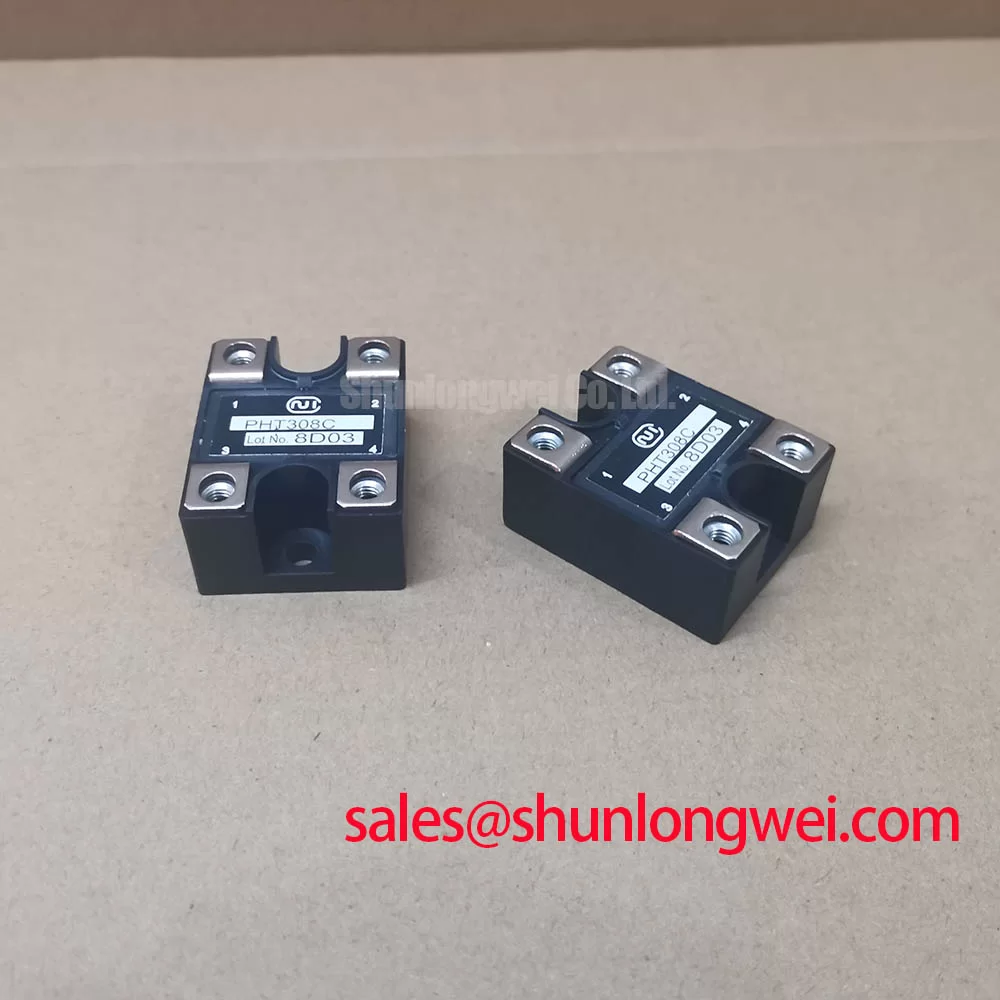
With the power isolated and stored energy discharged, check the PHT308C terminal markings against the equipment schematic before measuring cold-state impedance across its main terminals. A low reading alone does not identify a failed module: connected bus components and the meter’s test polarity can change the result. Record the readings in both polarities, inspect the enclosure and terminal hardware, and compare the results with a known-good assembly where available.
The confirmed factory parameters identify the Nihon Inter (NIEC) PHT308C as an isolated power module with a 1200 V rated voltage and 30 A rated current (Official Specification). Those ratings establish an initial identification boundary, not an allowable surge waveform or mounting instruction. The provided specifications do not state a non-repetitive surge on-state current, its starting junction temperature, a 10 ms half-cycle test condition, or the interval required before reverse voltage is reapplied. A repair engineer should obtain the full manufacturer datasheet before treating any surge figure as an acceptance limit.
For a candidate medium-frequency induction melting or hardening furnace power stage, first trace the module’s actual position in the equipment schematic. Confirm the terminal functions and current path against the original installation rather than inferring them from the product category. Check the heatsink contact surface for distortion or debris, and compare terminal orientation, mounting holes, and conductor clearance with the removed assembly. As a Design Consideration, thermal contact and joint integrity matter most when the stage sees repeated heating cycles; the equipment’s measured duty cycle and cooling arrangement determine whether its junction-temperature limits can be met.
A semiconductor fuse cannot be selected from the 30 A rating alone. The coordination record below identifies the evidence needed before a surge or fault-clearing decision; it supplies no unverified PHT308C limits.
| Coordination item | Required check |
|---|---|
| Module surge withstand and I²t | Confirm the manufacturer’s stated waveform, initial temperature, and rating in the complete PHT308C datasheet. |
| Fuse pre-arcing and total-clearing I²t | Use the selected fuse manufacturer’s data at the applicable voltage and prospective fault current. |
| Installed fault path | Verify source impedance, protective-device placement, and interruption behavior in the equipment. |
Field Alert: Isolate and discharge the equipment before loosening a terminal, and use the original mounting documentation for tightening torque rather than assuming a value for this module.
Field Diagnostics & Commissioning: Reverse Recovery Charge in PHT308C Topologies
During a cold-state check, separate the suspected module electrically where the maintenance procedure permits; otherwise, parallel components can mask an abnormal reading. Log meter polarity, terminal pair, and whether the module remains connected to the circuit. A discrepancy may justify further testing, but it does not establish a failure mechanism by itself. Recheck the equipment schematic before applying power, particularly where a neighboring rectifier or controlled device shares a bus connection.
Reverse recovery peak current and recovery time depend on the conducting device, current history, and commutation conditions. Neither an Irrm nor a trr value is included in the confirmed PHT308C parameters, and the module’s internal circuit arrangement is not established here. Do not assign it a diode soft-recovery characteristic on that evidence. As a Design Consideration, an engineer investigating turn-off loss or radiated noise should capture the installed voltage and current waveforms, identify which device is commutating, and compare the results with the relevant manufacturer specifications. An observed spike could involve recovery, wiring inductance, or another part of the circuit; the waveform and circuit path are needed to distinguish them.
For comparison work, the PGH50N16 page can be reviewed alongside the PHT308C documentation, but its electrical ratings, circuit arrangement, terminals, and mechanical fit must be independently verified before any substitution decision. The same discipline applies to an adjacent power-stage device such as PK55FG120: its place in the schematic determines whether its measurements are relevant to the fault.
If the furnace control panel reports a fault that cannot be reproduced at the power stage, verify the displayed message against controller logs and measured signals before condemning the module. Display technology is a separate diagnostic path: The Ultimate Guide to Industrial TFT LCD Technology provides TFT context, while references on optoelectronics and OLED displays explain display principles. None supplies a switching or recovery rating for PHT308C.
PHT308C Circuit Protection & Reliability: RC Snubber Network Optimization
Before changing an RC snubber, photograph its connections and identify the nodes it spans. Measure the installed resistance and capacitance with the circuit safely isolated, then inspect for loose joints or visible heat damage. A snubber fitted across one switching path cannot be assumed to protect every device on the bus. The confirmed 1200 V rating (Official Specification) is useful for identifying PHT308C, but it does not specify allowable transient peaks under the equipment’s operating conditions.
As a Design Consideration, minimize the relevant commutation-loop impedance where turn-off overshoot is observed. The system engineer should then select and validate any snubber components against measured switching waveforms, component temperature, and the original circuit requirements. A series saturable reactor deserves the same circuit-specific review: its presence or absence cannot be inferred from the module model, and adding one without evaluating the firing and commutation sequence could alter equipment behavior. No resistance, capacitance, reactor characteristic, or permitted dv/dt is established by the supplied PHT308C parameters.
Inspect the terminal area while tracing that loop. The enclosure is identified as an isolated power module (Official Specification), but that description does not provide a dielectric test voltage or prove that the installed conductor spacing satisfies the equipment’s insulation requirements. Check creepage paths, air clearances, insulating barriers, and lug placement against the original equipment drawings and applicable system requirements. This is an installation assessment, not a claim of certification for the module.
PHT308C Circuit Protection & Reliability: Preventing Localized Gate Hotspot Burnout
Gate-drive analysis begins with identification: verify from the full PHT308C manufacturer documentation and the equipment schematic which terminals, if any, are gate connections and what controlled device is inside the module. The provided voltage, current, and package parameters do not establish a gate pulse rise-time requirement, back-porch holding current, or multi-pulse firing specification. Applying a pulse target borrowed from another thyristor assembly would therefore be an unsupported commissioning step.
If the documented circuit does include a gate-fired device, a practical check is to observe the firing signal at the module terminals while monitoring the associated main-circuit waveform under the equipment maker’s approved test procedure. Compare pulse presence, timing, and repeatability with a known-good channel and the specified gate limits. A pulse seen at the controller output but not at the module directs attention to the intervening wiring and driver; it does not, on its own, prove damage inside PHT308C. As a Design Consideration, the driver and protective network should be evaluated together under the actual commutation conditions before changing pulse shape or firing strategy.
Keep protection methods tied to the verified device type. Desaturation sensing, VCE(sat) monitoring, and short-circuit safe-operating-area checks belong to IGBT system assessments; they cannot be assigned to PHT308C from the confirmed module parameters. For this repair, document the terminal map, measured firing signals where applicable, protective-device data, and cooling condition before returning the power stage to service.