

Content last revised on September 21, 2026
PK160F-160 Product Identification and Pre-Installation Checks
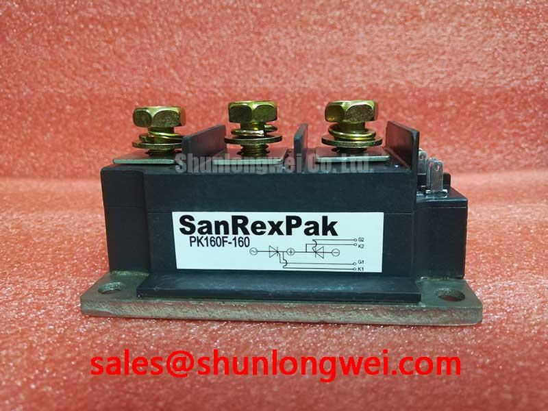
Before installation, verify the nameplate rating, inspect the isolated housing for cracks or contamination, and compare each power-terminal conduction path with the original circuit documentation using a meter’s diode-test function. The PK160F-160 from SanRex (Sansha Electric) is specified as an isolated power module with an official blocking-voltage rating of 1600V and a rated current of 160A. These are Official Datasheet Specifications and establish the electrical identity that must match the installed module before a high-voltage soft-starter assembly is returned to service.
| Parameter | Specified Value | Status |
|---|---|---|
| Model | PK160F-160 | Official identification |
| Manufacturer | SanRex (Sansha Electric) | Official identification |
| Rated voltage | 1600V | Official Datasheet Specification |
| Rated current | 160A | Official Datasheet Specification |
| Housing style | Isolated Power Module | Official Datasheet Specification |
Benchtop Waveform Tuning: Mitigating Stress via Gate Trigger Current Temperature Dependence on PK160F-160
For a phase-controlled starter repair, begin with a cold, de-energized terminal check and retain the measured results as a comparison record before applying any firing pulses. A diode-test reading can help identify whether the expected power paths are present, but the result must be compared against the original schematic or a known-good assembly because external snubbers, balancing parts, and parallel connections can affect the observed reading.
Gate firing quality should be evaluated at the driver output and at the module connection point with suitable isolated test equipment. Gate-trigger current, pulse rise time, holding behavior, and multipulse timing are system-dependent items that must be verified from the original SanRex documentation and the soft-starter control design. They are not established by the published 1600V, 160A, and isolated-module identification alone. A slow or distorted firing pulse can be associated with driver impedance, connector condition, control-board supply stability, or timing logic; waveform comparison against a known-good channel is more useful than assigning a single cause.
💡 Bench Tip: Keep static terminal readings and firing-waveform traces from a known-good unit as the cold-state reference, and use ESD-controlled handling before reconnecting control wiring.
Mounting torque, thermal-interface treatment, and terminal tightening must follow the applicable original module and equipment documentation. As a Design Consideration, uneven clamping or poorly prepared contact surfaces can alter thermal transfer and complicate fault isolation, so the heatsink surface, hardware condition, and terminal contact cleanliness should be inspected together.
Field Diagnostics & Commissioning: Semiconductor Protection Fuse Selection in PK160F-160 Topologies
In a high-voltage three-phase motor solid-state soft starter, semiconductor fuse coordination is assessed against the complete protected path rather than the module current rating alone. The 160A official rating identifies the module’s rated current class, while fuse selection requires the manufacturer’s time-current and clearing-energy data, the starter topology, prospective fault current, cable impedance, and the withstand information for every semiconductor in the affected branch.
During commissioning, inspect the fuse links, holders, bus connections, and control interlocks before energized testing. Where a fuse has operated, avoid treating the fuse as the only failed item. Check for shorted semiconductor paths, damaged surge-suppression components, carbon tracking, loose terminal hardware, and abnormal gate-drive behavior before fitting a replacement fuse. The clearing I²t figure must be compared with the relevant device withstand limit using source documentation; no specific coordination value should be assumed for PK160F-160 without the applicable SanRex data.
Engineers evaluating a hardware replacement should confirm the terminal arrangement, electrical function, isolation requirement, mounting footprint, and qualified protection network. The PD25016A can be reviewed as a documented alternative candidate, but it requires full circuit-level verification rather than a rating-only substitution.
Benchtop Waveform Tuning: Mitigating Stress via AC Input Transient Overvoltage Clamping on PK160F-160
Capture phase-to-phase input conditions and the voltage across the installed protection network before altering an AC transient clamp. The 1600V rating is an Official Datasheet Specification for the PK160F-160, not a complete surge-design prescription for the starter. Input transients are influenced by supply impedance, contactor operation, cable routing, motor characteristics, and switching events elsewhere in the panel.
As a Design Consideration, MOV and RC snubber networks should be evaluated as part of the full input and semiconductor commutation path. Their ratings, placement, energy capability, and failure mode must be selected by the system engineer after measured switching tests verify peak voltage margins. The commonly referenced surge-immunity framework is IEC 61000-4-5; it does not by itself certify an individual power module or prove the immunity of a finished soft-starter panel.
For product-family context, SanRex publishes power-semiconductor information through its power semiconductor module resources. Comparable module and diode technology references are also available from Shindengen Power Semiconductors. These references support component research but do not replace the original equipment circuit specification.
PK160F-160 Operational Boundaries: Evaluating Power Factor Degradation and Harmonic Limits
Phase-angle control in an AC motor soft starter changes the conduction interval supplied to the motor, which can change input current shape, reactive demand, torque response, and line harmonics. The firing-angle range used by the controller is a system operating decision. Although a controller may command a broad range from near zero to high delay angles, the usable range must be validated against motor load behavior, bypass-contactor sequence, supply conditions, and the installed protection scheme.
A practical commissioning check is to compare all three phase currents and firing waveforms during the controlled-start period, then verify the transition to bypass operation where applicable. Unequal current waveforms may indicate a timing, connection, sensing, or power-path issue and should be investigated with the equipment schematic and calibrated instruments. The PK160F-160 should remain within its official 1600V and 160A ratings under the verified system duty cycle.
For integration methods covering gate-drive layout, thermal interfaces, protection topology, and measurement discipline, see IGBT Design & Integration. Those general principles should be adapted and tested for the actual thyristor or diode module topology rather than applied as fixed settings.