
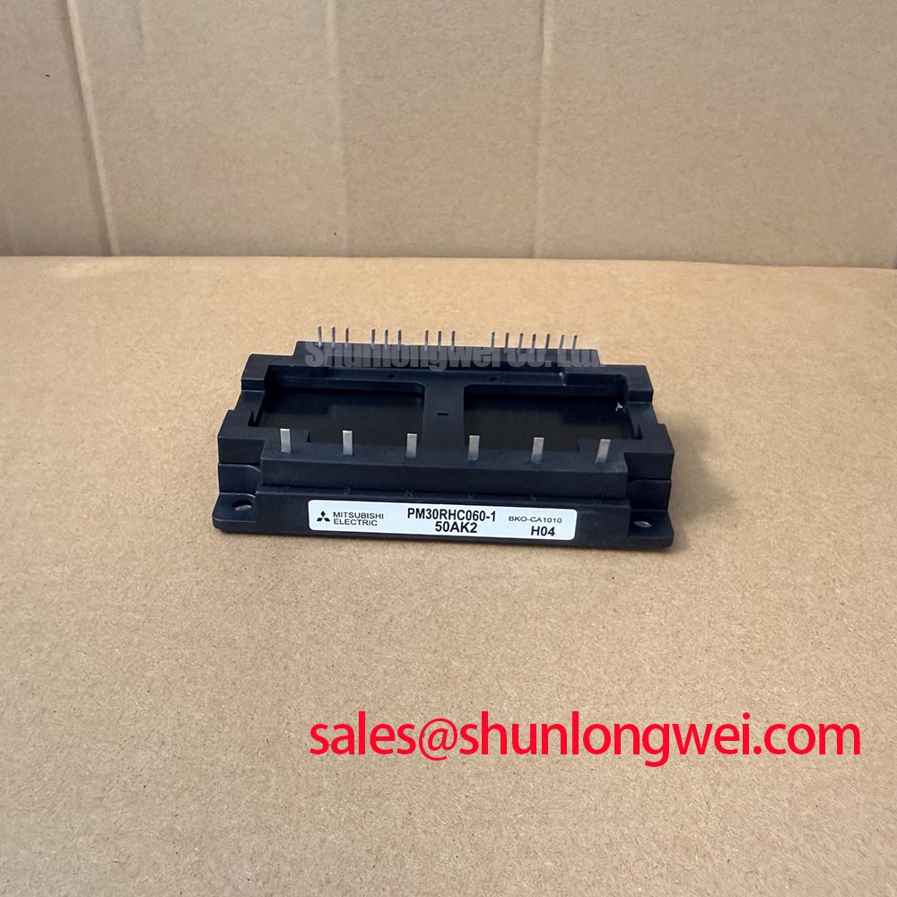


Content last revised on September 17, 2026
PM30RHC060-1 Operational Boundaries: Evaluating Fault-Clearing Dynamics: Type-I/II Desatur Limits
| Manufacturer | Mitsubishi Electric |
| Product Model | PM30RHC060-1 |
| Category | IPM Intelligent Power Module |
| Collector Emitter Voltage | 600 V Official Datasheet Specification |
| Collector Current | 30 A Official Datasheet Specification |
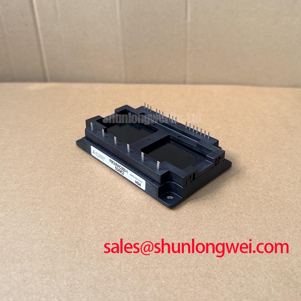
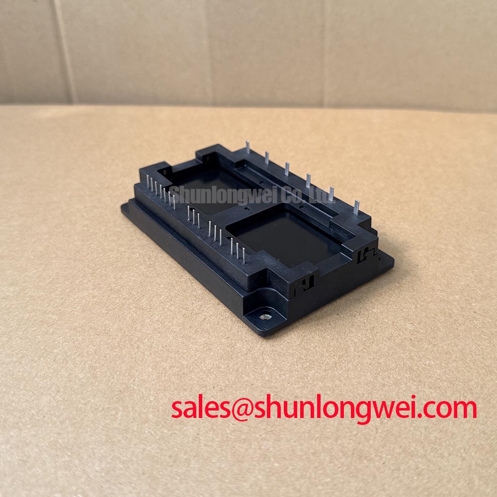
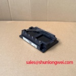
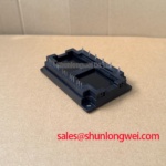
| Package | Mitsubishi IPM Module |
| Topology | General Power Stage |
| Series | Standard |
With the power removed and the DC link discharged, measure for an unintended low resistance path between the main power terminals before reconnecting a PM30RHC060-1 assembly. A result that differs materially from a known healthy drive board can indicate a damaged power path, a failed surrounding snubber, or a conductive contamination path, but the measurement alone does not identify the failed element. Inspect the module body, terminal interfaces, nearby bus bars, driver connector, and DC link capacitors as one electrical system.
The PM30RHC060-1 is rated at VCES = 600 V and IC = 30 A as Official Datasheet Specifications. Those ratings define the component identity and establish the electrical boundary that must be preserved when evaluating a failed precision stepper or BLDC motor servo motion actuator. They do not establish a universal DC bus voltage, switching frequency, overload duty, gate drive setting, protection delay, or cooling requirement. Those conditions belong to the installed drive system and require validation at the actual operating point.
During a short circuit investigation, capture the command signal, phase current indication, DC link response, and the driver fault signal with appropriate isolated measurement equipment. A desaturation or overcurrent circuit is intended to recognize abnormal current before the power stage leaves its safe operating region. Type I and Type II short circuit terminology is often used in power-electronics engineering to distinguish a fault applied while a device is already conducting from a fault arising during a switching event. The exact response capability, detection timing, and protection behavior must be verified from the original drive documentation and its protection circuit design; they are not stated by the supplied official PM30RHC060-1 product data.
Design Consideration: A fault shutdown path should avoid an uncontrolled hard interruption of current in an inductive motor circuit. A controlled soft turn off strategy can reduce the rate at which current collapses, helping limit inductive voltage overshoot. The appropriate gate discharge path, fault blanking logic, and shutdown profile are determined by the driver architecture, motor cable inductance, DC link layout, and measured switching waveform. Confirm peak voltage margins against the DC link voltage during switching tests rather than assuming a protection setting is suitable because it worked in another drive.
For a board-level repair, compare the fault behavior with a known healthy channel where available. Confirm that the isolation barrier is intact, the fault return path reaches the controller, and the controller actually removes PWM after a fault assertion. A repeated trip may relate to a genuine load event, sensor scaling, a damaged current feedback circuit, unstable gate drive supply rails, or waveform disturbance at the protection input. This is why a scope capture across the full event is more useful than treating a single fault code as proof of one cause.
The physical current path deserves the same attention as the protection circuit. Keep the high-current commutation loop compact to suppress turn-off inductive overshoots, then validate the result by measuring the switching transition with a suitable probe arrangement. For broader context on power-stage switching topologies and efficiency assessment, technicians evaluating inverter behavior can consult Peak Efficiency in Solar and Energy Storage. That resource is useful for evaluation principles, while the PM30RHC060-1 installation must remain governed by the host equipment's original electrical design.
Assembly Integrity & Layout Architecture: Implementing Baseplate Convexity Compensation and Screw for PM30RHC060-1
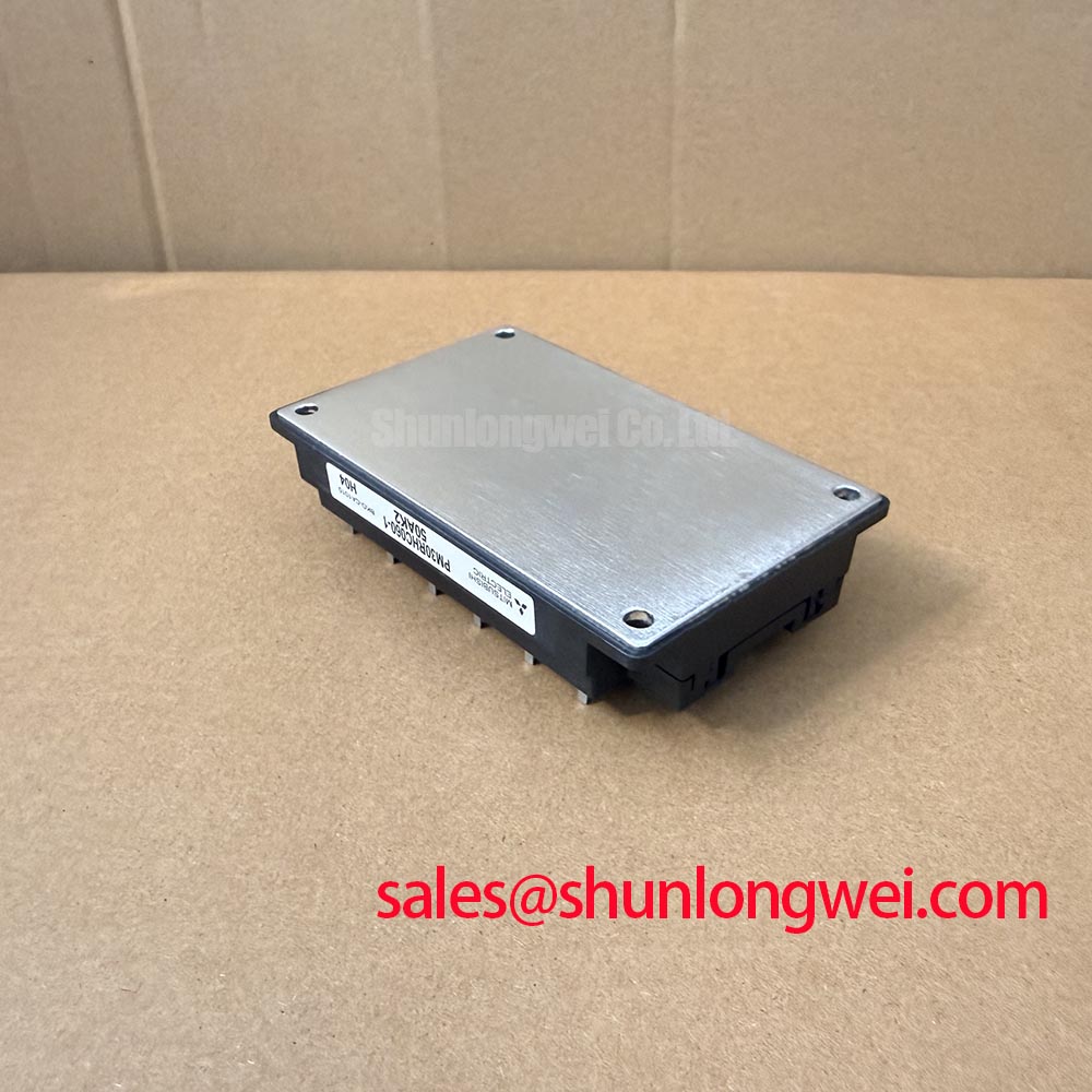
Place a straightedge across the mating heat sink area and inspect the removed thermal interface imprint for gaps, dry regions, debris tracks, or uneven transfer before installing the replacement module. Poor contact can create localized thermal stress even when the external heat sink appears cool and the drive initially operates normally. Clean both contact surfaces using an approved process for the equipment, examine the heat sink for burrs or damage, and ensure the mounting surface is flat enough for the module interface.
The supplied official identification defines a Mitsubishi IPM Module package, but it does not provide mounting hardware dimensions, screw type, mounting torque, baseplate flatness, thermal impedance, junction temperature limit, or thermal interface material specification. Do not assign those values to the PM30RHC060-1 without the applicable Mitsubishi mechanical documentation. The system integrator should verify the original module drawing, heat sink hardware, and production service instruction before applying clamping force.
Design Consideration: Thermal interface material must fill microscopic surface variation without becoming a thick thermal barrier. In industrial power-module service practice, a controlled thin and uniform bond line is the objective. The exact material, application quantity, and acceptable thickness are determined by the module drawing, heat sink condition, clamping arrangement, and thermal validation results. A baseplate that has slight curvature requires even pressure distribution; forcing one mounting point down first can distort the contact pattern and leave another area poorly coupled to the heat sink.
Install mounting fasteners in a crosswise sequence, increasing clamp load in stages according to the equipment service specification. After the mechanical joints are secured, verify that power terminals and control connector interfaces are not carrying mechanical strain from rigid bus bars or cable routing. A bus bar that pulls a terminal sideways can change contact pressure after thermal cycling and can introduce stress into the module housing. Keep the power loop mechanically supported and allow the module terminals to align naturally with the intended conductor geometry.
Field Alert: Disconnect and confirm the DC link is discharged before loosening power terminals, then apply mounting torque only to the original equipment specification with thermal interface material spread uniformly.
Thermal diagnosis should use evidence from the completed assembly. Compare heat sink temperature, airflow condition, cooling path cleanliness, fan operation where present, and the load profile before assuming that the power module itself is the sole source of heating. A transient thermal impedance network describes how a short load pulse and a longer duty interval produce different junction responses, but usable peak junction assessment depends on the actual loss waveform, the module's official thermal data, the heat sink path, and ambient conditions. Without that complete information, assigning a numerical junction margin would be unsupported.
For a same-class reference during a documented compatibility review, PM30CNA060 can be examined alongside the original system bill of materials. This reference does not establish a drop in replacement. Terminal arrangement, control interface, protection functions, thermal behavior, and host drive logic must all be verified before any alternate module is considered.
Preventing Spurious Faults: Galvanic Gate Drive Isolation, Reinforced Guidelines for PM30RHC060-1
Probe the gate command reference and fault signal at the driver board while the affected axis performs a controlled low-risk motion test, then compare the waveform against an unaffected axis or known-good signal path. A command that appears correct at the controller can arrive distorted at the driver because of grounding, isolation, connector contact, supply decoupling, or return-path problems. Check the driver connector seating and inspect the PCB around isolators, optocouplers, digital isolators, gate-drive supplies, and fault feedback traces for heat damage or contamination.
Galvanic isolation separates the low-voltage control domain from the switching power domain, helping prevent high common-mode movement from being interpreted as a command or fault event. Design Consideration: The isolation technology, creepage arrangement, clearance arrangement, and common-mode transient immunity must be appropriate for the complete drive voltage, contamination environment, PCB construction, and controller interface. A statement that an installed channel has reinforced isolation or a particular isolation withstand capability requires the original driver documentation or applicable certification evidence; it cannot be inferred from the PM30RHC060-1 voltage rating alone.
A spurious trip or unintended pulse can arise from several overlapping conditions. Examine the gate drive supply during switching, inspect the control return routing, and determine whether the fault occurs at a repeatable electrical transition. A current probe on the phase conductor, together with voltage and command captures, can separate a real load transient from a signal-integrity issue. When the symptom moves after exchanging a proven external driver card under a controlled service procedure, the result can guide the next inspection, but it still requires confirmation against the original circuit diagram.
Keep high di/dt power conductors physically separated from low-level sensing and gate-control paths wherever the host layout permits. The purpose is to reduce magnetic and capacitive coupling into sensitive command and protection circuits. The final routing arrangement is system-determined and should be tested under the intended DC link condition, motor cable configuration, and switching state. Avoid extending a gate command return through a power current path, because shared impedance can alter the voltage reference seen by the driver.
Where the host board includes separate control reference connections, preserve their intended routing and connector order during service. Do not invent a Kelvin emitter connection, auxiliary terminal function, or internal pin assignment from a visually similar module. Verify terminal designations from the original drive schematic and module documentation. Mitsubishi Electric publishes power semiconductor information through its Global Semiconductor Device Technologies resource, which provides useful product-family context without replacing the exact documentation required for a legacy equipment repair.
Benchtop Waveform Tuning: Mitigating Stress via Derating Guidelines and Mismatched Parameters on PM30RHC060-1
Record phase current, DC link voltage, gate command behavior, and heat sink condition while bringing the repaired actuator through a controlled sequence of low-load and expected-load tests. Look for unequal phase behavior, abnormal ringing, delayed current response, or fault activity that coincides with commutation. These observations may indicate wiring asymmetry, a gate-drive issue, a current-sensing concern, motor cable effects, or a mechanical load problem. Confirm the suspected path with comparison measurements instead of assigning a single cause from one waveform feature.
The 600 V and 30 A ratings remain the Official Datasheet Specifications for the PM30RHC060-1. Derating is a system-level engineering process, not an additional fixed PM30RHC060-1 rating. Designers should establish operating margin from the installed ambient environment, cooling performance, switching losses, pulse profile, bus voltage variation, control strategy, and official thermal and safe-operating documentation. A service bench should reproduce the equipment's relevant electrical conditions only when the test controls and measurement capability are adequate.
In parallel current paths, IGBT conduction characteristics can support static current sharing under certain operating conditions because VCE(sat) commonly has a positive temperature coefficient in the relevant current region. This is a Design Consideration, not a guarantee of equal sharing for this module in every circuit. Dynamic sharing depends heavily on symmetrical gate-loop wiring, matched driver behavior, power-path impedance, switching timing, and the operating waveform. The system engineer should verify current balance with suitable measurement tools under the real switching conditions.
Keep corresponding gate-drive paths geometrically consistent where the circuit uses parallel or matched switching positions. The aim is to reduce variation in parasitic inductance and resistance that can make one path switch earlier or absorb more transient energy than another. Gate resistance selection, driver output impedance, negative bias policy, and damping network values are system-determined. Any adjustment should be followed by waveform verification for overshoot, oscillation, switching loss, current balance, and fault response across the intended operating range.
When a servo drive contains a rectifier and DC link ahead of the PM30RHC060-1 power stage, assess input-side behavior separately from motor-side switching behavior. The conduction angle of a phase-controlled rectifier, source impedance, DC link condition, and load demand can affect line current shape and harmonic content. Avoid treating a motor phase-current anomaly as proof of a rectifier problem, or vice versa. Measure at the relevant point in the energy path and compare against the documented system topology.
For applications involving freewheel paths or external diode assemblies, component selection must follow the original power-stage schematic, electrical ratings, thermal design, and reverse-recovery requirements. Mitsubishi Electric provides a Diode Modules Lineup for product-family reference. It does not establish that a separate diode module is required, suitable, or interchangeable within a PM30RHC060-1 host system.