


Content last revised on March 28, 2026
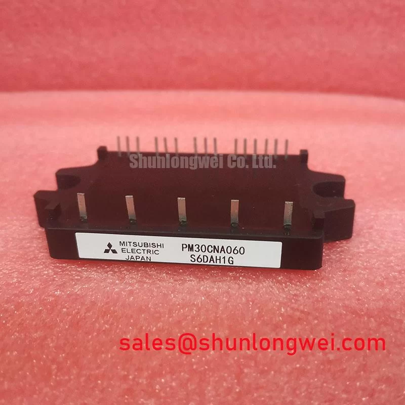
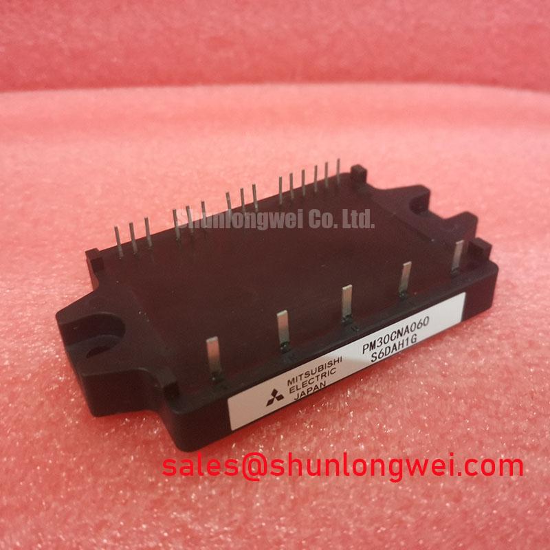
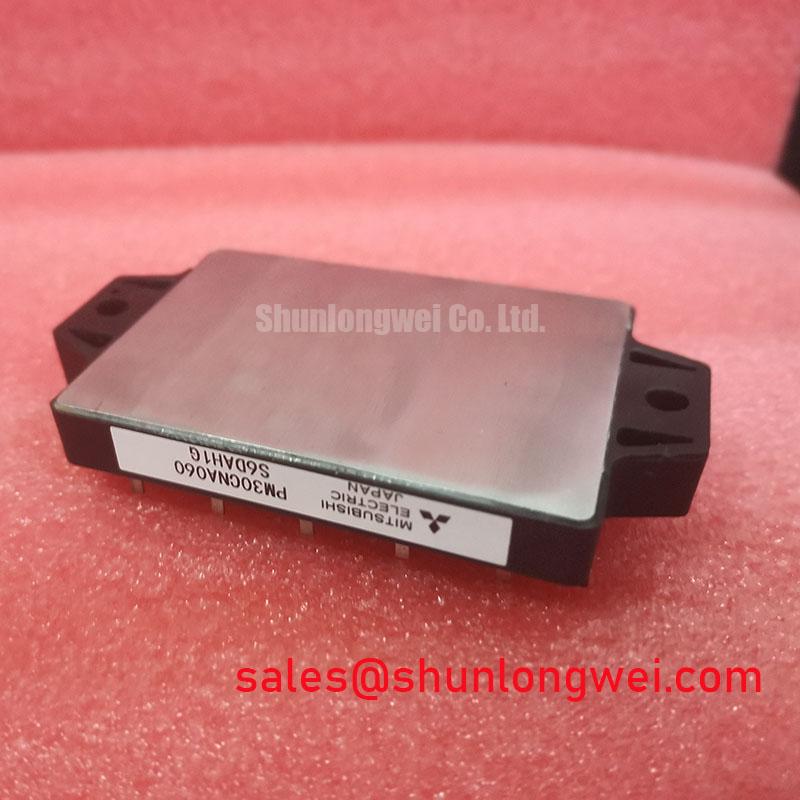
Mitsubishi PM30CNA060 | Integrated 600V/30A IPM for Accelerated, Reliable Motor Drive Design
In modern power electronics, the line between a component and a subsystem is blurring. The Mitsubishi PM30CNA060 is a prime example of this evolution. It is not merely a set of IGBTs; it is a fully integrated Intelligent Power Module (IPM) that combines a three-phase inverter power stage with the crucial gate drive and protection circuitry. This level of integration directly addresses the engineering pressures of reducing design cycles, minimizing board space, and enhancing system-level reliability for low-to-medium power motor control applications.
By embedding the gate drive logic, level-shifting, and protection functions within the same package as the power switches, the PM30CNA060 mitigates many of the parasitic inductance and noise susceptibility issues that plague discrete designs. This pre-engineered solution allows design teams to focus on system-level control and application logic, rather than the intricate and often problematic details of gate drive optimization and fault protection implementation.
Core Advantages of Integrated Design
The true value of the PM30CNA060 lies in its ability to abstract away complexity while delivering robust performance. Two key integrated features exemplify this design philosophy.
Comprehensive On-Board Protection
A discrete IGBT design requires numerous external components to protect against destructive events. The PM30CNA060 internalizes this, providing a shield against the most common failure modes:
- Short-Circuit (SC) Protection: The module can detect a short-circuit condition and safely shut down the IGBTs, preventing catastrophic failure.
- Over-Temperature (OT) Protection: An integrated temperature sensor monitors the module's substrate temperature, triggering a fault signal and shutdown if it exceeds safe limits.
- Control Supply Under-Voltage (UV) Protection: This ensures the gate drive voltage is sufficient for proper IGBT operation, preventing weak gate drive that can lead to increased conduction losses or damage.
This built-in protection suite not only saves significant PCB real estate but also offers a faster, more reliable response than most microcontroller-based monitoring schemes, ensuring the power stage is protected at all times.
Actionable Fault Signal (Fo) Output
Beyond self-protection, the module communicates its status back to the main system controller via a dedicated, open-collector fault (Fo) output pin. When any of the internal protection circuits (SC, OT, or UV) are triggered, the Fo pin signals the fault. This allows the system's microcontroller to initiate a graceful shutdown, log the error type for diagnostics, and alert the user. This closed-loop feedback mechanism is critical for building truly robust and easily maintainable systems.
Key Electrical Characteristics
The following table outlines the essential performance parameters for the PM30CNA060.
| Parameter | Symbol | Conditions | Value |
|---|---|---|---|
| Collector-Emitter Voltage | VCES | - | 600 V |
| Collector Current | IC | TC = 25°C | 30 A |
| Collector Power Dissipation | PC | TC = 25°C, per chip | 89 W |
| Collector-Emitter Saturation Voltage | VCE(sat) | IC = 30A, Tj = 125°C | 2.2 V (Typ.) |
| Control Supply Voltage | VD | - | 15 V |
| Isolation Voltage | Viso | AC 1 minute, 60Hz | 2500 Vrms |
| Operating Junction Temperature | Tj | - | -20 to 150 °C |
Application Scenarios and Value
The PM30CNA060 is engineered for applications where reliability, compact size, and rapid development are paramount. Its integrated nature provides a distinct advantage in the following areas:
- Robotic Servo Drives: In multi-axis robotic arms, space is at a premium and electrical noise is a constant challenge. The compact footprint and high noise immunity of the PM30CNA060 simplify the design of distributed motor drives, leading to more precise and reliable motion control. For more insights into this application, explore our guide on IGBTs in robotic servo drives.
- Small Industrial Inverters: For general-purpose variable frequency drives (VFDs) under 7.5 kW, this IPM provides a robust and cost-effective power stage. A leading conveyor system manufacturer was facing challenges with inconsistent performance from their discrete IGBT designs. By standardizing on the PM30CNA060, they reduced their assembly time and eliminated a common failure point, improving overall product line reliability.
- Commercial HVAC Systems: The integrated over-temperature protection is particularly valuable in air handlers and condenser fan motors, which can operate in harsh thermal environments. The module ensures the system fails safely, preventing costly motor damage and system downtime.
Strategic Component Choice: IPM vs. Discrete Solutions
Choosing between an IPM like the PM30CNA060 and a discrete component solution involves a trade-off between customization and integration. A discrete approach using individual IGBTs and gate driver ICs offers maximum flexibility for circuit optimization but requires significant engineering expertise in layout, thermal management, and protection design. This path can be susceptible to noise-induced failures and parasitic effects if not executed perfectly.
The PM30CNA060, in contrast, offers a pre-validated, highly reliable power stage. It is the ideal choice for projects where time-to-market is critical, engineering resources are constrained, or where system robustness is the primary design driver. While a discrete design might offer a lower BOM cost in very high-volume scenarios, the IPM often results in a lower total cost of ownership when factoring in development time, PCB space, and long-term reliability. For applications demanding higher power, an alternative like the PM150CVA120-2 provides a similar level of integration at a higher current rating.
Implementation & Design Questions
1. What is the main benefit of the integrated bootstrap diodes and resistors?
The high-side gate drivers require a floating power supply. The PM30CNA060 integrates the necessary bootstrap diodes and current-limiting resistors for this function. This eliminates several external components per phase, simplifying the PCB layout and reducing the risk of component selection errors associated with the bootstrap circuit design.
2. How should the fault (Fo) signal be interfaced with a microcontroller?
The Fo pin is an open-collector output, meaning it requires an external pull-up resistor connected to the microcontroller's logic supply (e.g., +5V or +3.3V). A typical pull-up resistor value is between 4.7 kΩ and 10 kΩ. When a fault occurs, the Fo pin pulls the line low, which can be easily detected by a GPIO input on the MCU.
3. Is a negative gate voltage required for turn-off?
No, a key advantage of the integrated gate driver is its optimization for single-supply operation (0V / +15V). It is designed to prevent spurious turn-on due to Miller currents without the need for a negative bias voltage, further simplifying the power supply architecture.
The Mitsubishi PM30CNA060 represents a strategic choice for engineers developing compact and reliable motor control systems. Its integrated approach simplifies design, enhances protection, and ultimately accelerates the path from concept to production. To discuss how this IPM can be integrated into your next project or to explore alternatives for different power levels, contact our technical support team for expert guidance. For further reading on the advantages of integrated modules, see our analysis of IPM vs. Discrete IGBTs or the official resources from Mitsubishi Electric.