

Content last revised on September 10, 2026
Sharp LM64N731 Display Module Interface and Integration Checks
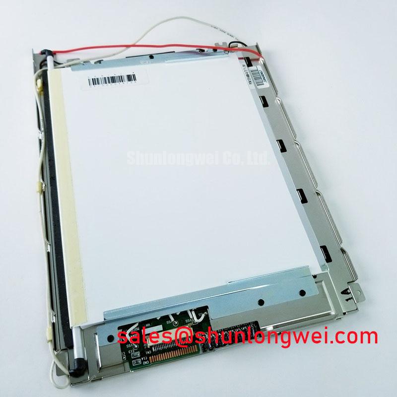
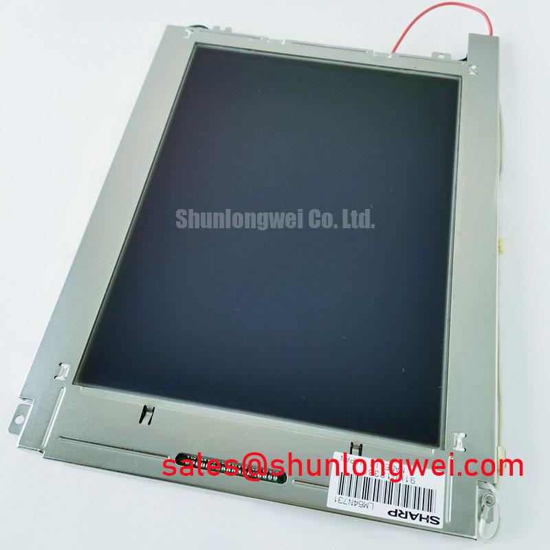
Before connecting a replacement panel, inspect the Sharp LM64N731 for visible damage, confirm the original equipment identification, and compare the panel connector and mounting interfaces with the service documentation. The available factory classification identifies this part as an Industrial Grade LCD/HMI Panel supplied as a TFT LCD Display Module by Sharp. Key interface voltage, resolution, luminance, connector pinout, dimensions, and backlight electrical data should be confirmed against the original panel documentation before installation.
| Parameter | LM64N731 Information |
| Model | LM64N731 |
| Manufacturer | Sharp |
| Product category | Industrial Grade LCD/HMI Panel |
| Display construction | TFT LCD Display Module |
| Specification status | Key interface and operating specifications require confirmation |
| Application assessment | Industrial HMI, railway passenger information, and cab signalling display replacement assessment |
Display Connector, Differential Signaling, Timing, and Skew Checks
The first compatibility check is physical rather than software based. Compare the installed panel’s FPC or FFC connector position, contact orientation, locking style, cable exit direction, and pin count with the replacement documentation. A connector that appears mechanically similar can still have a different power, enable, clock, or data arrangement. The system integrator should verify whether the host uses a 20 pin or 30 pin interface and should not assume that the LM64N731 shares a pin assignment with another Sharp display.
The supplied factory information identifies the LM64N731 as a TFT LCD display module but does not provide a confirmed LVDS voltage, data mapping, timing table, pixel resolution, or connector pin definition. These values must be taken from the original panel documentation or an approved equipment drawing. In particular, verify the required logic supply voltage rather than assuming a common rail. The host controller must also be checked for signal format, lane count, clock polarity, and data order.
JEIDA and VESA mappings are not interchangeable in every display system. An incorrect mapping can produce swapped colour channels, abnormal grey levels, misplaced image data, or a split-screen appearance even when the panel receives power. During a repair, compare the known-good panel waveform and the replacement-panel waveform at the transmitter and receiver sides. Confirm the pixel clock relationship, data hold behaviour, enable sequence, and signal integrity across the intended operating temperature window. If the image shifts, flickers, or shows intermittent bands, investigate cable seating, mapping, clock quality, and return-current paths together instead of assigning the symptom to a single cause.
Power sequencing also needs to be treated as a system requirement. The supplied engineering outline references a logic supply rise-time window of 0.5 ms to 10 ms, but this should be handled as an integration condition to verify against the applicable panel documentation, not as a confirmed LM64N731 factory rating. Measure the supply ramp, display enable timing, reset behaviour, and backlight enable relationship during cold start and normal restart. A controller that enables the interface before the panel supply has stabilised may create an apparent display fault that is actually caused by system sequencing.
For differential display-link routing, maintain a controlled differential path and preserve the intended pair relationship through the connector, cable, and host board. The engineering outline identifies 100 ohms differential characteristic impedance as a routing target. This is a design consideration for the complete transmission path, not a standalone LM64N731 specification. Designers should verify impedance continuity, pair polarity, skew, termination, and common-mode behaviour with the selected cable and transmitter. When a replacement cable is required, its contact orientation and shielding construction should match the original assembly.
In a railway passenger information system or cab signalling display, service technicians should validate the panel using the actual controller, not only a generic bench adapter. The controller’s differential-link transmitter may have different clock jitter and data timing margins from the equipment used during a previous repair. A stable test image, several grey-scale patterns, and a moving diagnostic pattern can expose mapping errors and marginal clock conditions more effectively than a static logo.
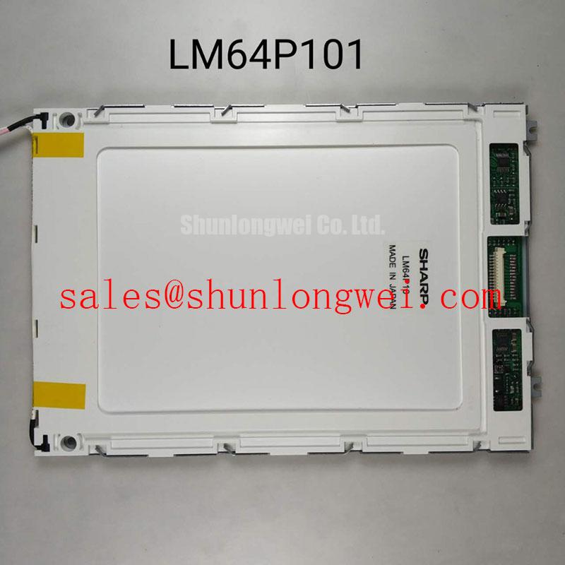
For a same-size or same-resolution replacement assessment, engineers may also review LM64P10 as a separately documented alternative display option. It should be evaluated from its own mechanical, optical, electrical, and timing documentation rather than treated as an automatic substitute for the LM64N731.
Industrial EMI Noise Immunity, Chassis Shielding Continuity and Common Mode Ferrite Chokes
Noise troubleshooting should begin with cable placement and bonding. Route the display-link cable away from inverter output wiring, motor phases, relay coils, and high-current switching loops where the enclosure permits. A display installed near a variable-frequency motor drive can experience common-mode disturbance through cable shields, chassis joints, supply returns, or poorly bonded access panels. Horizontal noise bands, pixel jitter, and occasional loss of synchronisation should therefore be checked against drive switching activity and cable movement.
A shielded display-link or FFC assembly requires a continuous return path from the display-side shield termination to the controller-side chassis reference. The exact bonding method depends on the equipment’s isolation and EMC architecture. Designers should inspect the complete shield path at every connector transition and enclosure seam rather than relying on a shield that is connected at only one visible point. A 360-degree termination is a common industrial design consideration where the connector and enclosure construction support it, but the final arrangement must be validated against the system’s safety and EMC design.
Common-mode ferrite chokes can be considered when conducted interference is present on the differential cable. Selection is system dependent because an unsuitable component can add unwanted differential loss, reduce signal margin, or alter the edge behaviour of the link. The choke should be evaluated with the actual transmitter, cable length, receiver, and operating temperature range. Oscilloscope measurements at the receiver should be compared with a known-good signal path before and after any filtering change.
Backlight control requires the same discipline. The supplied design outline identifies a PWM dimming range of 200 Hz to 1 kHz for evaluation, but this is not confirmed as an LM64N731 factory specification. The system integrator should verify whether the panel uses a dedicated backlight driver, an external constant-current stage, analogue brightness control, or a PWM input. Do not apply a guessed backlight voltage or current to an unverified display connector.
Check duty-cycle linearity using the complete brightness-control chain, including the host processor, isolator, driver, cable, and display. Visual flicker can be affected by PWM frequency, camera exposure, optical persistence, and control-loop behaviour. Audible noise may also come from the external driver or magnetic components rather than the LCD itself. Record brightness commands, actual backlight current, enable timing, and display temperature during the test so that a repeatable service baseline is available.
When an external backlight solution is being reviewed, the LMS700KF01-001 can be considered as a separately listed complementary display-related device. Its electrical role and compatibility must be confirmed independently from the LM64N731 documentation. The two products should not be connected together without a verified wiring diagram and electrical interface review.
⚠️ Field Alert: Disconnect system power and allow stored energy to discharge before removing or inserting the display cable, because an unlocked or live FFC connection can damage the interface or create intermittent contact.
Backlight Thermal Dissipation and Light Guide Preservation
The available factory data does not confirm the LM64N731 backlight type, luminance rating, LED current, optical plate material, or L70/B50 life data. These values must not be inferred from the product category. If the original equipment uses an edge-lit LED assembly, inspect the complete backlight arrangement before selecting a replacement driver or modifying the mechanical frame.
Thermal review should focus on the heat path from the backlight components to the enclosure. A metal spreader rail can be considered along the active edge when the original assembly uses a thermally coupled edge structure. The rail must not press against the optical stack, obstruct the light path, or create a local mechanical load. The enclosure designer should verify contact pressure, insulation, thermal expansion, and service access through testing on the complete display assembly.
Bright edge-lit displays can show local luminance variation when one section of the backlight operates at a different temperature from another. Observe the panel during warm-up, steady operation, and controlled restart. Check the bezel, rear cover, cable routing, and nearby heat sources for locations that could create a local hot spot. The display module’s operating behaviour should be assessed together with the backlight driver because driver losses and switching conditions may dominate the thermal result.
Optical preservation is also a mechanical issue. Avoid compressing the display layers, bending the panel frame, or trapping the FPC beneath a bracket. A panel that operates correctly on a bench can show dark areas, bright edges, or non-uniform fields after it is clamped into a metal housing. Use the original support points where possible and verify that gasket, bezel, and cable routing do not transfer enclosure stress into the display.
Long periods of static HMI content should be evaluated at the system level. LCD image retention can be influenced by temperature, drive conditions, displayed pattern, contrast settings, and operating time. Where the application permits, designers may use screen rotation, low-contrast standby graphics, or periodic content changes as a general design consideration. These measures are not a guaranteed lifetime specification for the LM64N731 and should be validated with the actual interface electronics and operating profile.
Cold-start testing deserves a separate record. At low ambient temperature, measure the time from power application to stable image, backlight enable response, touch or keypad interface readiness where applicable, and recovery after a rapid power interruption. The system controller may need a controlled retry or display-ready check, but the timing should be established from measured behaviour rather than a fixed assumption. Do not classify a slow image response as a panel defect until supply ramp, backlight enable, differential-link activity, and temperature have been checked.
For broader integration guidance covering industrial display enclosures, environmental evaluation, and HMI system architecture, engineers can consult Industrial Display and HMI Solutions. The referenced material should be used as system-level guidance rather than as an additional LM64N731 factory specification.
Thermal Expansion Clearance Sizing across Heavy Industrial Metal Enclosure Cutouts
Mechanical interchangeability begins with a drawing comparison. Verify the LM64N731 outline, active-area position, viewing direction, connector clearance, cable bend path, mounting-hole pattern, and bezel opening against the host equipment. The supplied factory summary does not include confirmed external dimensions or hole coordinates, so the original panel drawing remains the controlling document for any railway passenger information terminal or cab display repair.
A metal enclosure can impose stress on a display through thermal expansion, frame distortion, fastener preload, and vibration. The cutout should support the bezel without contacting the active display area or forcing the panel into a non-planar shape. Designers should allow clearance according to the enclosure material, temperature range, support geometry, and mounting scheme. The correct clearance is system determined and must be checked by dimensional inspection and environmental testing.
The supplied engineering outline references an M3 cross-pattern fastening torque of 0.35 N·m to 0.45 N·m. This is a general integration reference requiring confirmation against the panel drawing, fastener type, washer arrangement, thread engagement, and enclosure material; it is not presented here as a confirmed Sharp LM64N731 factory limit. Tighten progressively in a cross pattern only when the mounting documentation calls for that method, and inspect the image at each stage for changes in uniformity.
FPC reliability depends on bend radius, fixed-point placement, connector retention, and movement caused by vibration. Keep the flexible cable away from sharp chassis edges and ensure that the connector lock is fully engaged before securing the rear cover. The cable should not be used as a structural restraint. During vibration assessment, monitor the display image while gently checking the cable and connector area for intermittent response, then repeat the inspection after the assembly has returned to room temperature.
For outdoor-facing or brightly lit equipment, optical performance must be evaluated under the actual ambient illumination and cover-glass arrangement. The outline references a contrast target above 500:1 at 50,000 lux, but no confirmed LM64N731 contrast specification or anti-glare coating data is included in the supplied factory information. Engineers should verify contrast, reflections, viewing angle, and readability using the original optical stack, since cover glass, polariser orientation, surface treatment, and display brightness all affect the result.
Railway cab signalling and passenger information equipment may also experience vibration and shock transmitted through the mounting frame. The display should be supported evenly without creating isolated pressure points. Verify image uniformity before and after thermal cycling, cable retention, and enclosure installation. If optical mura appears only after fastening, release the panel, inspect the bezel opening and support pads, and repeat the installation with measured mechanical conditions rather than increasing clamping force.