

Content last revised on October 9, 2026
Liquid Crystal Threshold Voltage (V_th) Tracking across Industrial Operating Temperatures
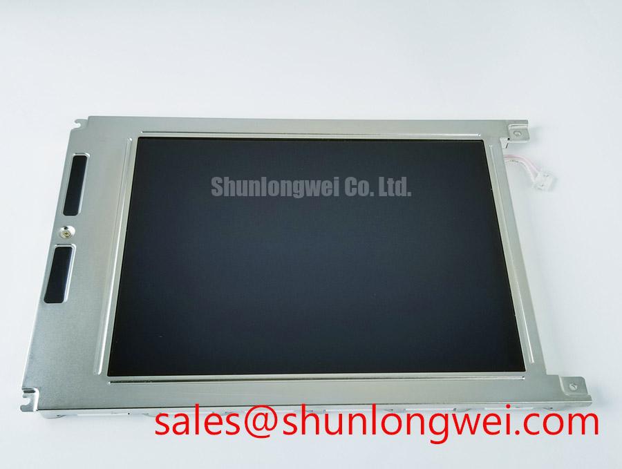
| Product model | LM64C06P |
|---|---|
| Manufacturer | Sharp |
| Product category | Industrial LCD/HMI panel |
| Technology baseline | STN passive matrix LCD |
| Electrical and mechanical limits | Supply voltage, resolution, dimensions, connector assignment, operating temperature, and illumination configuration: consult the model-specific datasheet. |
Measure the contrast-control rail at the panel connector while displaying a fixed test pattern, and record how the image changes as the assembly reaches thermal equilibrium. For LM64C06P integration, this separates temperature-dependent optical behavior from disturbances introduced by the host power supply. Design Consideration: passive matrix contrast depends on the relationship between the liquid crystal threshold and the applied drive waveform, rather than on the contrast adjustment alone.
Where the host schematic identifies V_ee or V_0, establish whether that node supplies a bias generator or directly controls the display operating point. These labels are not interchangeable across controller boards. Observe ripple with a short probe return and compare it with visible modulation under the same image pattern. A supply disturbance correlated with contrast fluctuation warrants investigation of the regulator, return path, and connector contact before changing the panel.
Design Consideration: if the host includes thermistor compensation, assess its response alongside the panel temperature rather than the enclosure air temperature alone. Sensor placement, thermal lag, and the compensation network can affect cold-start readability. Lower temperatures generally slow liquid crystal response; that behavior should not automatically be diagnosed as corrupted digital data. Compare static contrast with moving-pattern response to distinguish the two effects.
Persistent optical discoloration after temperature and bias have stabilized calls for a separate optical inspection. Do not attribute it to a particular polarizer chemistry without construction evidence. For replacement planning, compare the Sharp LM64C06P connector, controller requirements, and mounting drawing with the existing assembly. The LM8V30 provides another display reference for that comparison, not an established interchangeable replacement.
Direct Sunlight High-Ambient Readability without Active Backlight Illumination
Evaluate ambient-light readability with the illumination disabled and the panel held at the installed viewing angle, without treating a visible image as proof of a specified reflective or transflective construction. Record whether characters remain distinguishable as the light direction changes. This practical check identifies the contribution of ambient illumination while keeping the assessment separate from an unsupported sunlight-readability claim.
Design Consideration: cover-window reflections, surface contamination, and viewing geometry can reduce apparent contrast even when the display drive is stable. Compare the bare viewing surface with the assembled enclosure under equivalent lighting. If readability changes substantially after installation, examine window spacing, bezel alignment, and mounting stress before adjusting electrical contrast. A bezel pressing unevenly on the panel can also produce local optical changes.
Inspect for localized haze, edge discoloration, or visible bubbling using oblique illumination. These observations document an optical defect; they do not establish iodine degradation, adhesive chemistry, or ultraviolet damage as its cause. Cleaning should follow the approved surface procedure, with no solvent allowed to wick into exposed edges. Protecting the optical surface from unnecessary heat and direct exposure is a Design Consideration, not a model-specific environmental rating.
When assessing compatibility with an ultrasound console or surgical-navigation operator terminal, distinguish an auxiliary control display from a diagnostic image display. Mechanical fit and image presentation alone do not establish suitability for clinical image interpretation. The equipment owner should evaluate the original display requirements and applicable system validation. The Sharp Display Solutions Official Portal offers manufacturer context, but does not replace the exact module specification or the equipment’s acceptance criteria.
CCFL Inverter Strike Failure Localization: Differential Tube Aging vs. Ballast Transistor Breakdown
Establish from the installed illumination assembly whether CCFL inverter troubleshooting applies before measuring a strike waveform. The following procedure is a Design Consideration for a host assembly with documented CCFL illumination, not a declaration of the LM64C06P backlight construction. Trace the inverter input, enable command, lamp connection, and protection feedback on the equipment schematic.
Field Alert: Disconnect power and follow the equipment’s discharge procedure before handling display or illumination connectors. Energized inverter measurements require appropriately rated probes and the equipment’s specified service precautions. Investigate whether shutdown follows the enable command, lamp ignition attempt, or a supply interruption. Each observation narrows the fault path without assigning a single cause to a dark screen.
Design Consideration: lamp aging, damaged wiring, switching-device faults, and protection-circuit behavior can produce overlapping symptoms. Compare input supply stability and enable timing first, then inspect the inverter switching stage and lamp-side connections using the approved service method. Any known-good comparison assembly must match the required electrical configuration. Do not impose generic ignition voltage, operating current, or insulation-clearance values on an unidentified illumination circuit.
Keep illumination regulation separate from LCD contrast generation, while checking their interaction through shared supply and return paths. A disturbance during inverter startup can affect the host bias rail without proving a panel defect. The LM64P89 display reference can support comparison of another display assembly’s integration requirements; it should not be treated as a backlight driver or auxiliary power component. Broader environmental test planning belongs in the Industrial Display & HMI Solutions engineering resource, with acceptance limits taken from the equipment requirements.
Parallel Digital Signal Reflections Mitigation via Series Damping Termination Resistors
Map the controller signals to the actual panel connector before interpreting clock ringing or missing lines. In passive matrix interfaces that use FLM, LP, and CP labels, these commonly identify frame, line, and data-clock functions; the connector drawing determines their assignment and polarity. Do not apply LVDS differential-pair rules or JEIDA/VESA mappings to a parallel interface simply because those conventions appear on another display board.
Design Consideration: compare clock and data waveforms at the receiving connector, including edge quality and relative timing. Cable routing, return-path discontinuities, and connector transitions can create reflections that reduce sampling margin. Pro Tip: consider source-side series damping only after identifying the driving device and interconnect behavior, then validate the selected resistance against receiver timing during bench tests.
Assess startup and shutdown sequencing alongside the interface capture. The host should establish the required supplies and valid drive activity in the sequence specified for the panel, avoiding unintended sustained DC across the liquid crystal. This concerns drive-waveform balance and sequencing; it should not be described as liquid crystal “latch-up.” Compare an unsuccessful startup with a normal startup before changing controller delays.
For intermittent rows or columns, check external connector seating and cable strain relief before disturbing the panel assembly. Where a service drawing specifies an elastomeric contact, preserve its alignment and prescribed assembly compression rather than applying a generic pressure value. Clean exposed contacts only by an approved procedure compatible with adjacent materials. Finish the repair assessment by testing repeated startup, representative image patterns, and connector stability in the installed mechanical arrangement.