

Content last revised on September 22, 2026
Flush-Mount Open-Frame Bezel Integration & Perimeter Gasket Shock Isolation
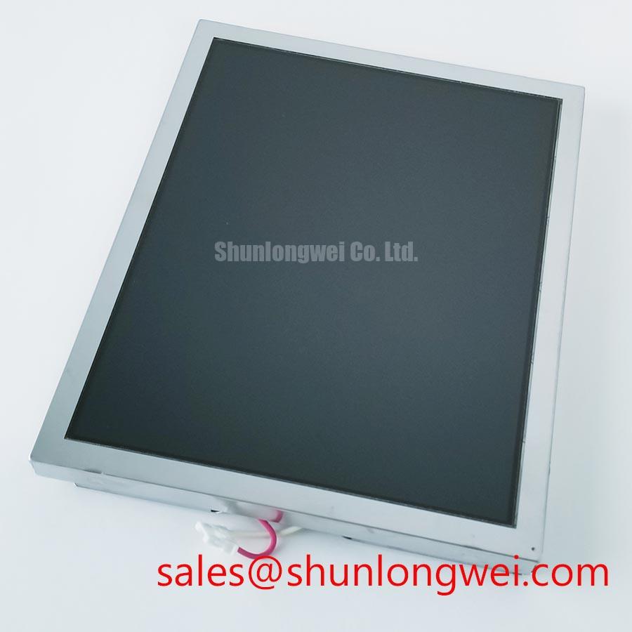
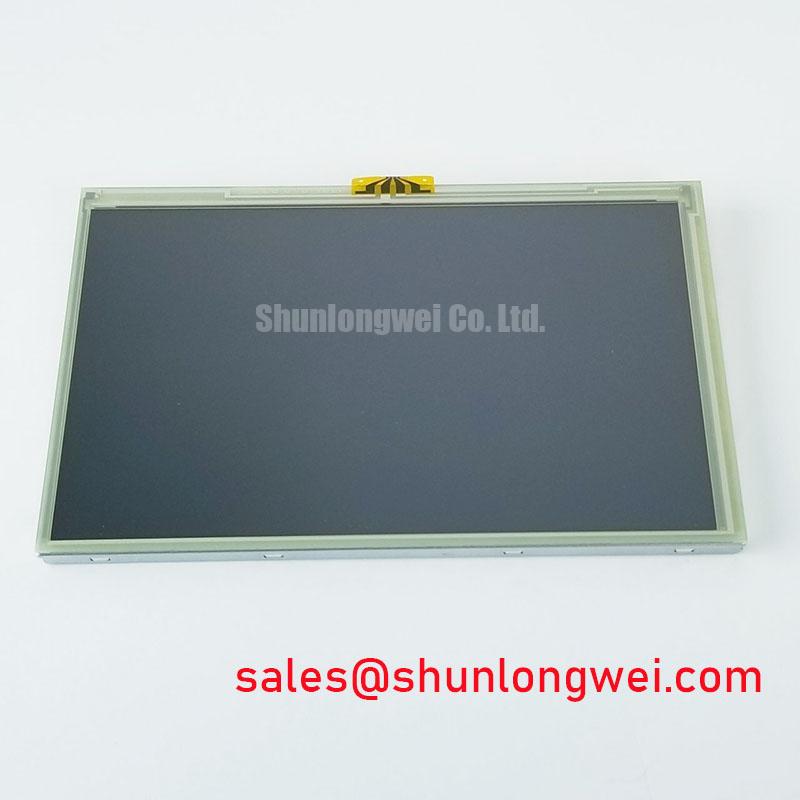
Begin mechanical evaluation by dry-fitting the A080SN03 V0 into the front bezel without applying force to the active display area. Check that the bezel opening clears the visible region, the panel frame rests on its intended support surfaces, and the connector or cable is not preloaded by the enclosure. Uneven contact around an open-frame panel can create local stress that becomes visible as brightness variation or dark-field mura during a full-screen test.
Use uniform white, gray, black, red, green, and blue test images after the panel is mounted. Observe the display from normal operating distance and at oblique angles, then compare the result before and after bezel tightening. A newly visible patch, pressure mark, or edge glow should be treated as an installation condition to investigate rather than attributed to a single cause. Check bezel flatness, gasket placement, support points, retained debris, and screw engagement.
Engineering Recommendation: use the equipment manufacturer's mechanical drawing and fastener requirements to establish the mounting method. Cross-pattern tightening can help distribute enclosure loading, but torque values and gasket compression must be determined by the chassis design and verified with the installed panel. Do not treat generic M3 torque guidance as an official specification of this AUO module.
Cold environments deserve a separate functional check. Liquid-crystal response can slow at low ambient temperature, causing transitions between gray levels to appear delayed or smeared. When an enclosure uses a heater strip or temperature-control method, its placement, sensor logic, warm-up behavior, and display safety limits should be validated at system level. The product information supplied here does not confirm an operating-temperature rating for the A080SN03 V0.
Bench Tip: Disconnect power before handling the display cable, then insert the cable squarely and secure its latch without twisting the connector or loading the panel edge.
Mitigating Gray-to-Gray Response Time Escalation during Cold-Start Machine Power-Up
During cold-start evaluation, use repeatable image content rather than judging motion from a single live SCADA screen. Alternating neutral gray patterns, moving cursor trails, alarm banners, and page changes can reveal whether sluggish transitions are present only during warm-up or remain after the enclosure reaches its normal controlled condition. Record the panel temperature, controller state, image pattern, and observation time so a later comparison is meaningful.
A slow or uneven image after startup can arise from several locations in the HMI chain. The panel temperature, host timing, panel supply sequence, cable seating, backlight behavior, and controller configuration should each be checked against a known-good path where available. Avoid assigning a response symptom to a single component without measurement. Oscilloscope checks of relevant power and interface signals, performed by qualified personnel using the host documentation, provide stronger evidence than visual inference alone.
Design Consideration: the stability of perimeter sealing and backlight performance across thermal cycling belongs to the validated display assembly and enclosure program. No LED backlight lifetime figure, brightness-retention point, sealant construction, or thermal-cycle rating is stated in the supplied official information for this model. Procurement and repair teams should request the applicable original documentation when these characteristics are acceptance requirements.
For field replacement work, compare full-screen luminance and color appearance with the original system's approved display state under the same enclosure settings. Apparent nonuniformity can be affected by front filters, viewing angle, protective windows, ambient light, and image source configuration. A controlled dark-room inspection followed by an installed-enclosure inspection separates panel observations from optical-stack effects.
VESA vs. JEIDA Data Mapping Alignment & Even/Odd Channel Signal Integrity
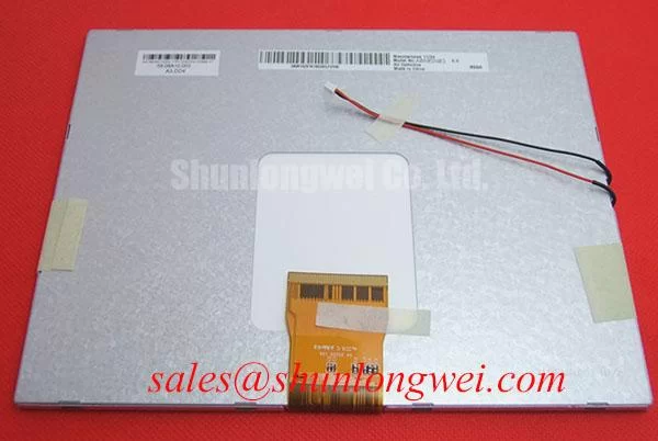
Before connecting the host cable, verify the connector part reference, pin count, mating orientation, panel-controller documentation, and cable keying. The supplied official product description confirms a TFT-LCD display module, but it does not confirm LVDS use, VESA or JEIDA mapping, even and odd channel assignment, logic voltage, or power-on timing for the A080SN03 V0. The system integrator should verify the required supply voltage from the original panel documentation.
Split images, incorrect colors, unstable pixels, or patterned artifacts can indicate several possible integration issues, including incorrect mapping, an incompatible timing source, marginal differential routing, a damaged cable, or an incomplete connector latch. Compare the host controller configuration and cable assembly to the known equipment specification. When measurements are appropriate, inspect the known-good and suspect signal paths with equipment suitable for differential display signals; interpretation should remain tied to the controller and panel documentation.
Design Consideration: controlled differential impedance and matched routing are common display-interface practices when the interface requires them. Their target values, termination arrangement, rise-time limits, and sequence requirements are system-determined and must be verified during switching and image tests. Do not apply generic interface values as an official AUO rating for this panel.
For projects evaluating a different display family, TCG084SVLQAPNN-AN30-S can be reviewed as a separate candidate. Its mechanical, electrical, optical, and controller compatibility must be assessed independently; it should not be assumed to be a direct replacement for A080SN03 V0. A related display solution, LQ10D321, should likewise be checked against the original system documentation before any integration decision.
Industrial EMI Noise Immunity, Chassis Shielding Continuity & Common-Mode Ferrite Chokes
In an installed console, examine image stability while surrounding equipment follows its normal operating sequence. Pixel jitter, intermittent horizontal bands, momentary blanking, and flicker may be associated with cable shielding, chassis bonding, grounding paths, power quality, controller behavior, or external electromagnetic conditions. Inspect connector retention, shield termination, cable routing, enclosure bonding surfaces, and the continuity of any shielding provisions specified by the original equipment design.
Engineering Recommendation: preserve the intended shield connection around the cable entry and avoid routing display cables alongside high-noise conductors where the enclosure design permits separation. Common-mode suppression components may be evaluated when system testing indicates a noise-coupling concern, but their selection and placement must be established through equipment-level testing. This individual TFT-LCD module is not represented as independently compliant with a complete-system EMC standard.
For consoles located near high-energy electrical equipment, verify display observations alongside the actual operating state of the host controller and enclosure. Qualified teams should follow the site safety process before accessing cabinet interiors. The provided product information does not establish high-voltage insulation performance, partial-discharge behavior, or dielectric certification for this display module. For broader engineering context on insulation mechanisms, see partial discharge and polyimide; neither reference substitutes for the display's original qualification documents.
For inspection methods that connect display symptoms to enclosure, cable, and HMI integration checks, consult Industrial Display & HMI Solutions. Retain the panel label, controller settings, observed test images, and equipment documentation with the repair record so later troubleshooting has a traceable baseline.