Content last revised on September 16, 2026
Preventing Spurious Faults: Junction-to-Heatsink Heat Dissipation Guidelines for PSMD 200E-12
Before reconnecting a cabinet, isolate the supply, inspect the module body and power terminals for cracking, corrosion, heat discoloration, loose hardware, or disturbed thermal compound, then verify that the installed nameplate matches PSMD 200E-12.
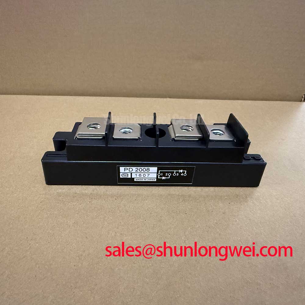
This Nihon Inter, also known as NIEC, power device is specified as a rectifier module with a 1200 V repetitive peak reverse voltage, 200 A average rectified output current at case temperature Tc = 96 degrees C, 2200 A surge forward current at 60 Hz for one cycle, 0.09 degrees C/W junction to case thermal resistance, and 2500 V AC isolation voltage for one minute. These are Official Datasheet Specifications and should be treated as the electrical and thermal boundary for replacement evaluation.
| Official specification | Value | Service relevance |
|---|---|---|
| Repetitive peak reverse voltage, Vrrm | 1200 V | Verify against the measured repetitive reverse blocking requirement of the installed topology. |
| Average rectified output current, Id | 200 A at Tc = 96 degrees C | Assess with the actual case temperature and load duty rather than a nominal cabinet current alone. |
| Surge forward current, Ifsm | 2200 A, 60 Hz, one cycle | Relevant to abnormal inrush and fault coordination studies, not continuous operating current. |
| Junction to case thermal resistance, Rth j-c | 0.09 degrees C/W | Shows why baseplate contact and heatsink condition require attention. |
| Isolation voltage, Viso | 2500 V AC, one minute | Check installation clearances and test procedures against the original equipment documentation. |
The published 0.09 degrees C/W value applies from junction to case, not from junction to ambient air. A system can therefore show an acceptable cabinet temperature while the module case interface is degraded by an uneven mounting surface, old compound, warped heatsink, or unequal clamping load. Design Consideration: clean both contact faces, inspect the heatsink for raised damage around holes, and spread thermal interface material as a continuous thin film according to the equipment maker's assembly instruction. The final thermal result is determined by the complete mounting stack, airflow, heatsink performance, load waveform, and ambient condition.
Field Alert: Tighten terminals and mounting hardware only to the original equipment or fastener manufacturer's torque requirement, because excessive or uneven force can distort the module base contact and create a localized thermal problem.
For a stopped SVC or thyristor switched capacitor assembly, compare the condition of each parallel or adjacent power position before replacing a single module. A visibly normal connection does not establish low resistance under load. Look for heat marks at busbar interfaces, reduced contact area caused by shifted washers, and cable lugs that can move after tightening. With power safely removed, a meter diode check across the accessible power terminals can identify a gross short or open condition, but its indication must be compared with the known circuit path because surrounding capacitors, snubbers, and parallel devices can affect the reading.
Where a repair review requires comparison with another industrial power semiconductor, PGH50N16 can be reviewed as a separate reference item. It must not be considered a direct replacement solely from a part-number comparison. Terminal arrangement, voltage class, current rating, thermal interface, control topology, and original circuit function all require confirmation.
Field Diagnostics & Commissioning: Type-2 Coordination for Sub-Cycle Dead Shorts in PSMD 200E-12 Topologies
When a branch fuse has operated, begin with the unpowered circuit: record the fuse designation, inspect the rectifier path, trace the connected busbars, and test the module only after energy storage elements have been discharged according to the equipment procedure. A low-resistance result can arise from a failed module, a downstream short, a connected capacitor bank, an associated thyristor branch, or measurement through parallel paths. Isolate connections where the maintenance manual permits and compare findings with a known-good phase or branch.
The 2200 A one-cycle surge forward-current rating is an Official Datasheet Specification for a defined sinusoidal surge condition. It is not a declared fault-clearing capability for an arbitrary protection system. Type-2 coordination requires the system engineer to compare the semiconductor fuse pre-arcing and total clearing I2t curves with the withstand limits of every protected semiconductor and with the prospective fault current at that exact installation point. The fuse body, holder, conductor arrangement, source impedance, and prospective short-circuit current all influence the result.
A practical commissioning record should retain the installed fuse part number, its time-current and I2t documentation, module location, busbar arrangement, and fault investigation observations. When the manufacturer data does not state an I2t withstand figure for PSMD 200E-12, do not substitute the 2200 A surge figure into an I2t calculation as though the two ratings were interchangeable. Request the original equipment protection-coordination documentation or obtain engineering approval before altering fuse selection.
In capacitor switching equipment, a diode module can be associated with charging, rectification, clamping, or auxiliary supply paths depending on the published circuit. A nearby controlled device such as PK55FG120 should likewise be assessed from its own datasheet and circuit duty. Its presence does not define the topology or establish compatibility with the PSMD module.
After a fault repair, inspect current paths before applying full energy. Verify that busbars are clean, mating faces are flat, insulation barriers are restored, and the fuse is seated correctly. Initial energized tests should follow the original equipment commissioning sequence, with current, voltage, and temperature monitored by qualified personnel. A repeat fuse operation may indicate unresolved stress elsewhere in the assembly and should trigger a circuit-level review rather than repeated module replacement.
Benchtop Waveform Tuning: Mitigating Stress via RC Snubber Network Optimization for PSMD 200E-12
Before modifying an RC snubber, document the existing resistor value, capacitor part number, lead routing, mounting position, and evidence of heating. The PSMD 200E-12 official data provided here defines its voltage, current, surge, thermal, and isolation ratings; it does not publish an approved snubber network or a device-specific switching slope limit. RC values must therefore not be assigned as a universal prescription for this module.
Design Consideration: minimize the physical loop area of the current path that includes the snubber, associated switching device, and busbar connection to reduce inductive overshoot and ringing. The system engineer should measure the relevant waveform with an appropriate high-voltage differential probe and current measurement method, then verify peak voltage against the installed DC link, circuit tolerances, and the 1200 V Vrrm limit under realistic operating transitions. Probe placement matters; a long ground lead or distant measurement point can create a waveform that does not represent stress at the module terminals.
RC snubbers and series saturable reactors are system-level elements. Their purpose can include controlling voltage rise, damping resonant behavior, and limiting the rate of current change in a specific switching path. Whether they are required, and what component values they use, depends on transformer leakage, busbar geometry, capacitor-bank behavior, switching devices, wiring length, load state, and the protection strategy. Changes should be tested across the operating states authorized by the equipment design, with component temperature and voltage waveform evidence retained.
A ringing event after replacement does not automatically prove that the replacement module caused it. Check terminal orientation against the original schematic, torque and contact integrity, polarity of connected components, snubber continuity, and whether a removed busbar or cover altered the current-loop geometry. If waveforms indicate an unresolved reverse-recovery or commutation concern in a surrounding diode or thyristor path, review the device behavior and circuit timing using source documentation. Background on charge storage and recombination can be found in carrier lifetime, but it is general semiconductor theory rather than a published switching parameter for PSMD 200E-12.
PSMD 200E-12 Operational Boundaries: Evaluating Power-Factor Degradation and Harmonic Mitigation Limits
For a grid-tied static var compensator or thyristor-switched capacitor installation, start analysis from the actual one-line diagram and firing-control records. The supplied specification identifies PSMD 200E-12 as a 1200 V, 200 A rectifier module; it does not publish firing-angle data, gate-trigger characteristics, harmonic limits, power-factor curves, or a declared role inside an SVC branch. Those system results cannot be attributed to the module without the original circuit design.
When engineers evaluate a controlled rectifier or thyristor-related branch over firing angles from zero to 150 degrees, the change in conduction interval can alter displacement factor, reactive power demand, input-current shape, and harmonic content. The exact transfer characteristic depends on the AC source, transformer connection, commutation reactance, capacitor configuration, control algorithm, load, and the installed semiconductor topology. Use measured current and voltage waveforms, synchronized firing references, and the applicable utility or site requirements to determine whether observed power-factor degradation originates in firing control, an unavailable capacitor step, commutation overlap, a failed semiconductor path, or another system condition.
The module's 200 A rating at Tc = 96 degrees C should be assessed against measured case temperature and actual rectified current waveform. Harmonic current can raise RMS heating in conductors, fuses, transformers, and semiconductor paths even where average current appears ordinary. Design Consideration: validate current sharing and thermal behavior at the equipment's permitted operating states, then compare findings with the original protection and cooling design.
Repeated thermal cycling is a package-level reliability concern in power assemblies, particularly where load cycling changes the temperature difference between operating states. The general mechanism is described in this reference on thermal fatigue and power cycling. It does not provide a service-life prediction for this specific module. For broader device-selection context involving newer power-semiconductor technologies, see the Wide Bandgap Revolution engineering guide; any migration or topology change requires a separate system compatibility assessment.