
Content last revised on October 28, 2026
SD15M60AC Thermal-Electrical Optimization: Preventing High di/dt Gate-Loop-Induced Transients: Practical Tuning
Isolate the drive, verify that its DC link has discharged, and compare the installed SD15M60AC terminal connections with the equipment schematic before taking cold resistance measurements. Record the measurement polarity and disconnect parallel paths where the service procedure permits; surrounding capacitors, diodes, and driver circuitry can otherwise distort a module-level assessment.
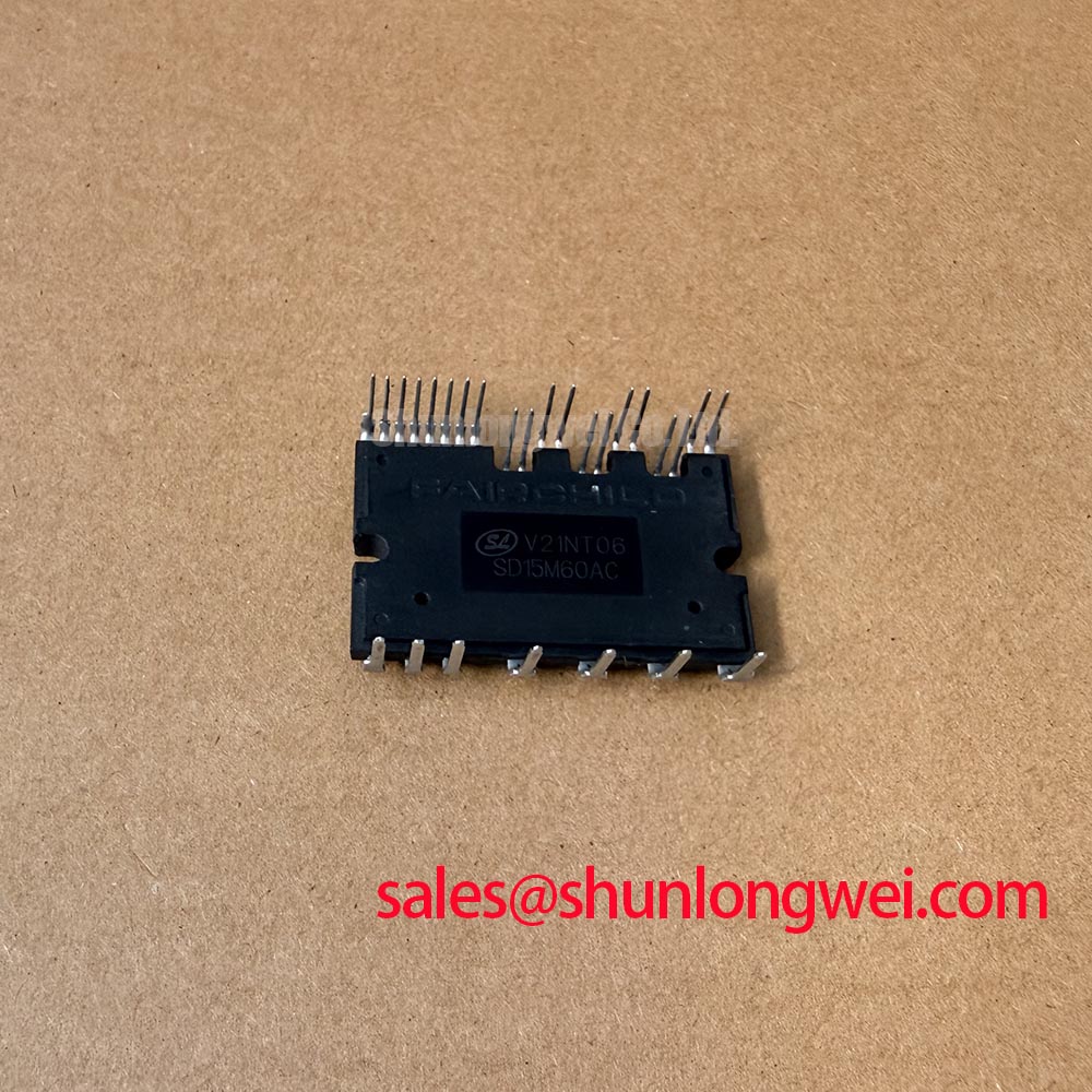
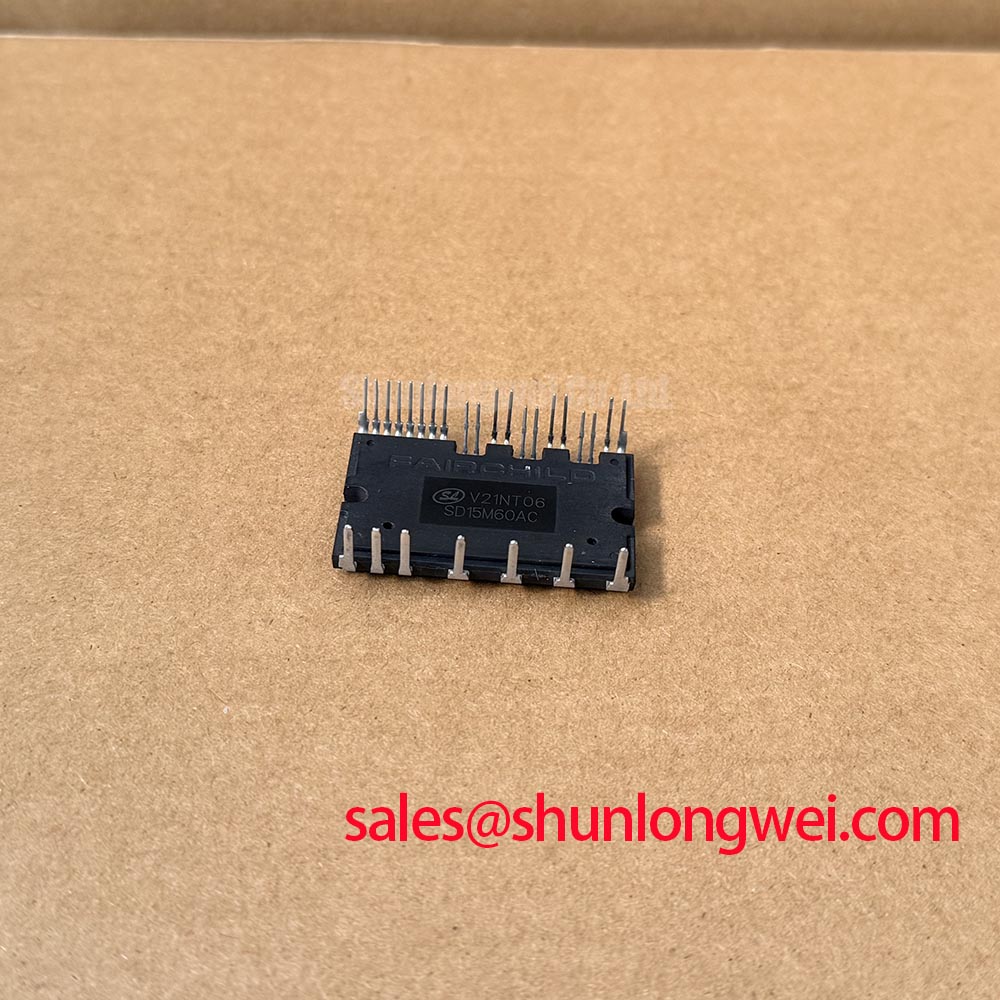
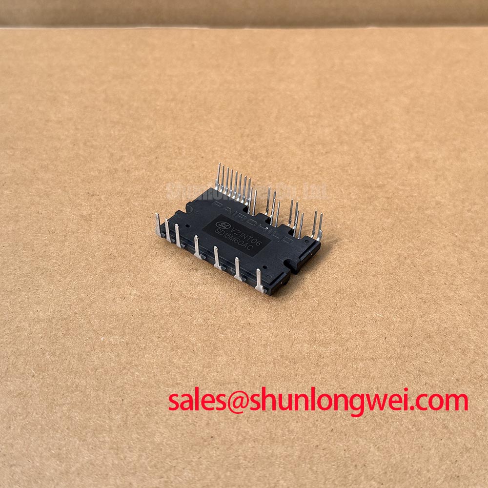
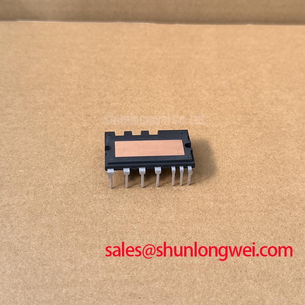
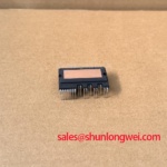
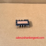
The SD15M60AC is identified here as a power semiconductor module. Replacement assessment should connect the exact part marking to the terminal drawing, electrical ratings, and mounting requirements rather than infer specifications from the model number.
Trace the driver return connection on the schematic before interpreting any apparent gate disturbance. Design Consideration: a main load emitter connection carries switching current, whereas a separately documented auxiliary emitter connection provides a driver reference. Treat these as different circuit functions only when the terminal drawing explicitly identifies them; an auxiliary Kelvin emitter must not be assumed for the SD15M60AC.
Where the equipment provides a dedicated driver return, check that repairs have preserved its original routing. Shared conductor impedance can introduce a voltage disturbance into the gate reference as load current changes. A longer replacement wire or a relocated return connection can therefore change the observed gate waveform without any change to the control command. Compare the repaired assembly with the original layout, including connector seating and return-path continuity.
For powered measurements, use appropriately rated differential or isolated instrumentation and reference the gate measurement to the driver’s intended emitter connection. Observe the command, gate response, and switching-node transition together. An apparent oscillation should be checked against probe-loop pickup before changing circuit components. Keep measurement connections compact and away from the commutation path.
Engineering Recommendation: evaluate gate damping through controlled changes to the documented driver network, checking switching stress and temperature together. Increasing damping can reduce ringing but can also increase switching loss; the acceptable balance belongs to the complete driver and power-stage design. The Precision Gate Drive Design guide provides supporting discussion for evaluating return paths and switching-loop interactions, rather than a substitute for the SD15M60AC terminal documentation.
Benchtop Waveform Tuning: Mitigating Stress and Preventing Overvoltage Trips During Fast Switching in the SD15M60AC
Separate a sustained DC-link rise during deceleration from a short switching overshoot before changing the braking circuit or gate network. Capture the bus-voltage envelope alongside the switching waveform and the drive’s braking command. These observations distinguish an energy-management problem from a local commutation disturbance more reliably than the overvoltage fault message alone.
Design Consideration: motor deceleration can return energy to the DC link. Assess the braking switch and resistor at equipment level using the machine’s stored energy, stopping profile, repetition rate, and permitted bus-voltage excursion. Do not assign an internal braking transistor to the SD15M60AC without a confirmed circuit diagram. Check an existing braking resistor’s connections, thermal protection, and documented duty capability before attributing repeated trips to the power module.
For fast transients, examine the commutation path and any documented freewheeling devices. Diode recovery interacting with circuit inductance can contribute to voltage ringing and electromagnetic emissions. Probe placement matters: a waveform collected through a large measurement loop can exaggerate the disturbance. Compare repeatable measurements at consistent operating conditions before evaluating changes to an existing snubber.
Engineering Recommendation: select or adjust snubber components through the equipment’s validated design process, checking voltage stress, pulse dissipation, and thermal behavior. A quieter waveform at one test point does not establish system EMC compliance. Preserve separation between power-current paths and sensitive control wiring according to the equipment’s electrical safety and layout requirements.
For a potential heavy-duty variable-frequency AC motor drive replacement, use the following compatibility checks before treating matching markings as sufficient evidence of interchangeability. The supplied voltage and current descriptions are classification text, not numerical electrical ratings.
| Compatibility item | SD15M60AC information | Installed assembly comparison |
|---|---|---|
| Product identity | SD15M60AC; manufacturer not specified in the supplied information | Match the complete equipment parts record |
| Package classification | Module | Compare mounting drawing and terminal locations |
| Working voltage | Consult datasheet; supplied description: Standard Industrial Rating | Compare documented blocking limits and operating conditions |
| Rated current | Consult datasheet; supplied description: Standard Operating Current | Compare rating conditions and thermal requirements |
| Driver interface | Consult terminal and circuit drawings | Match gate connections, return routing, and protection interface |
Motor type also belongs in the compatibility review: BLDC commutation and permanent-magnet synchronous motor drives provide useful background on control and commutation, but neither establishes suitability of this module for a particular controller.
Preventing Spurious Faults and Ceramic Substrate Rupture: Guidelines for SD15M60AC
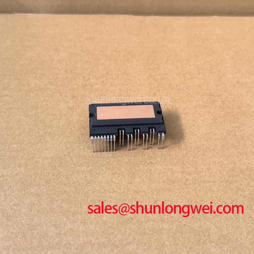
Inspect the mounting interface for debris, raised damage, residual compound, and uneven seating before tightening the SD15M60AC onto the heatsink. Assess surface condition against the applicable mechanical drawing rather than attempting to flatten the module by bolt force. Baseplate material, permitted curvature, and internal substrate construction require documented confirmation; they should not be inferred from the module category.
Design Consideration: uneven clamping can impair thermal contact and impose mechanical stress on a power-module assembly. Where the mounting instructions specify multiple fasteners and staged cross-pattern tightening, use a calibrated tool and follow that sequence. Check that washers, screw engagement, and mounting hardware match the assembly requirements. Electrical terminal fasteners and heatsink mounting screws serve different functions and should not share an assumed torque value.
Field Alert: Never use mounting screws to pull an unevenly seated module flat against the heatsink.
Apply thermal interface material using the approved material and application method, maintaining an even contact layer without contaminating terminals or seating surfaces. Thickness is an assembly-specific requirement, not a universal setting. During service, inspect the removed interface pattern for incomplete contact, displaced compound, or localized contamination, then address the mechanical cause rather than simply adding more material.
Engineering Recommendation: assess repetitive thermal loading using the documented transient thermal impedance and actual loss profile when those data are available. Case temperature alone does not establish peak junction temperature during a short load pulse. After reassembly, compare temperature behavior under repeatable operating conditions, inspect the interface and cooling path if the trend changes, and retain the measured operating conditions with the service record.