
Content last revised on October 27, 2026
SKD51/16 Thermal-Electrical Optimization: Pulse-Transformer Isolated Firing Circuit Practical Tuning
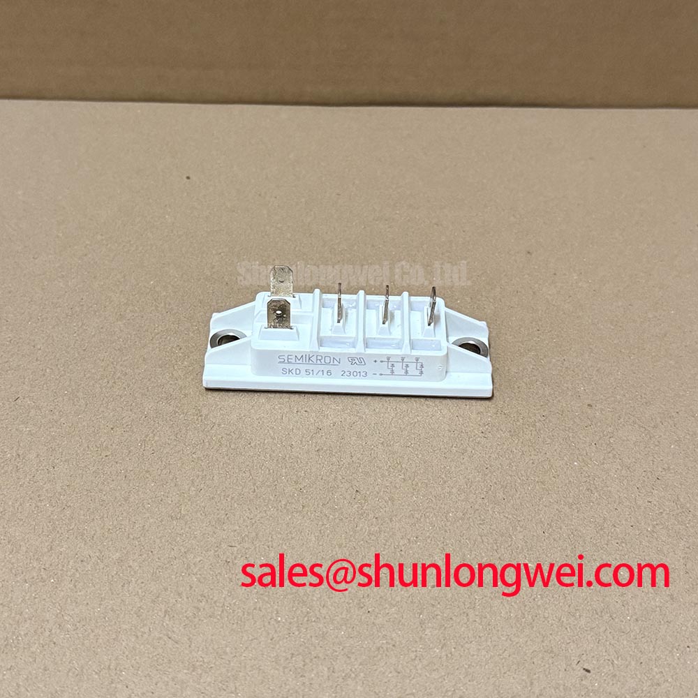
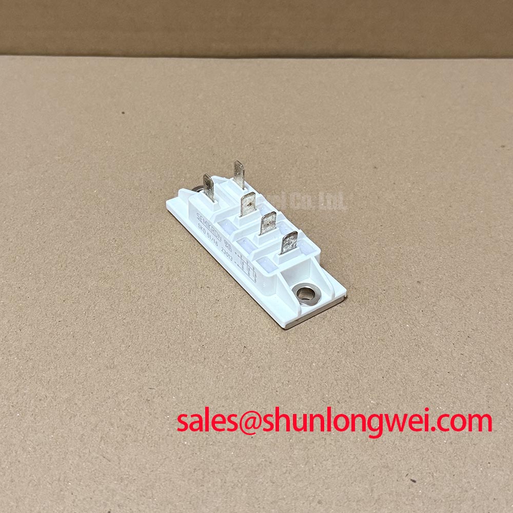
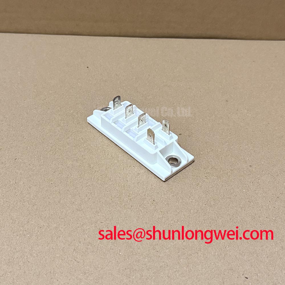
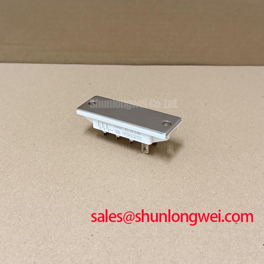
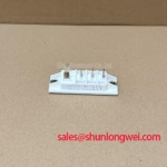
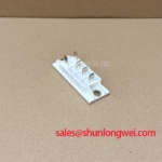
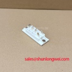
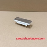
Model: SKD51/16 | Manufacturer: Semikron | Category: Bridge Rectifier Module | Package: Semipont | Rating verification: Supplied values of 600.0 V and 511.0 A are not established here as official datasheet specifications; consult the manufacturer’s model-specific datasheet before electrical selection.
I check the terminal diagram before connecting a firing-circuit tester: a bridge rectifier must not be treated as a gate-controlled thyristor module. For the SKD51/16, procurement and maintenance records should identify the bridge function separately from any controlled switching stage elsewhere in the equipment. Gate pulse rise time, back-porch current, and pulse-train triggering are not appropriate acceptance criteria for an uncontrolled rectifier bridge.
Design Consideration: When tracing a cabinet that contains pulse transformers, follow their secondary connections to the actual controlled devices. A nearby rectifier can share the cooling assembly or power circuit without receiving firing signals. Negative gate bias, gate-trigger voltage, and gate-trigger current belong to the relevant controlled semiconductor’s documentation, not automatically to the SKD51/16.
At the rectifier, concentrate on terminal identification, conductor condition, and the thermal interface. Match the marked AC and DC connections to the equipment schematic before disturbing busbars. Record the original hardware arrangement, inspect mating surfaces for contamination or distortion, and apply the mounting and terminal tightening instructions specified for the exact module and assembly. Do not transfer a torque value from a visually similar package.
For replacement assessment, the SKD210 is a separate comparison candidate, not an established interchangeable replacement. Circuit configuration, blocking ratings, current test conditions, terminal geometry, and mounting dimensions must agree with the equipment requirements before substitution is considered.
Maintenance Note: Trend terminal temperature and inspect cooling airflow during planned maintenance, with physical tightening checks performed only after safe isolation and discharge.
Preventing Spurious Faults: Evaluating Post-Surge Reverse-Voltage Blocking Guidelines for SKD51/16
After a surge event, compare the captured current waveform and subsequent reverse voltage with the rectifier’s specified test conditions before authorizing another start. A non-repetitive surge rating describes a defined event; it is not permission for repeated overloads or unrestricted reverse-voltage reapplication while the junction remains hot.
Design Consideration: Evaluate surge duration, initial junction temperature, repetition, and the voltage imposed after conduction together. For a diode bridge, use the manufacturer’s diode surge-current designation rather than importing a thyristor rating by name. The applicable half-cycle duration and recovery conditions must come from the exact datasheet, not from a generic rectifier test convention.
On the equipment side, retain protection logs and examine phase-current balance, contactor operation, and charging-path behavior. An abnormal trace may involve the supply, connections, load, or rectifier; a single symptom does not establish the failed component. Compare observations with a known-good operating record under equivalent conditions.
Cooling condition matters during restart assessment. Inspect heatsink passages, fan performance, and accessible thermal-interface condition during scheduled shutdowns. Set inspection intervals from contamination exposure, operating history, and equipment instructions rather than assigning an unsupported module-specific service life. Where condensation is possible, restore the enclosure’s intended environmental controls before energization.
For potential use within a grid-tied static var compensator or thyristor-switched capacitor cabinet, establish the SKD51/16’s actual rectification role separately from the controlled reactive-power branch. A component such as SKD75GAL123D requires its own topology and interface assessment; its presence in related equipment does not establish a complementary pairing. The Semikron-Danfoss official hub provides the manufacturer reference point for product documentation.
SKD51/16 Thermal-Electrical Optimization: Fuse Total Clearing I²t versus Device Withstand Practical Tuning
Compare the selected fuse’s total clearing I²t with the rectifier’s specified withstand conditions at the actual circuit voltage and prospective fault current. Comparing current ratings alone misses the energy admitted while the fuse interrupts the fault. Pre-arcing I²t must not be substituted for total clearing I²t.
Design Consideration: Build the coordination record around the fuse manufacturer’s curves, the module’s surge limits, initial temperature, and circuit impedance. Include interruption capability and the equipment’s protective arrangement. This assessment supports protection selection, but it cannot guarantee zero damage during every short circuit.
During repair, inspect fuse contacts and adjacent busbar joints as well as the semiconductor mounting surface. Contact heating can complicate thermal observations and should be investigated separately from semiconductor conduction losses. Preserve terminal spacing and insulating barriers when restoring the assembly.
For equipment containing a multilevel converter, Peak Efficiency in Solar and Energy Storage offers system-topology context, not an SKD51/16 protection specification. Likewise, Semikron sintering technology describes a packaging technology and does not establish this module’s internal construction. Close the maintenance task by documenting the fitted fuse, connection checks, cooling condition, and controlled restart observations.