

Content last revised on October 23, 2026
SKD75GAL123D Operational Boundaries: Evaluating ITSM Safety and Repetitive-Use Limits
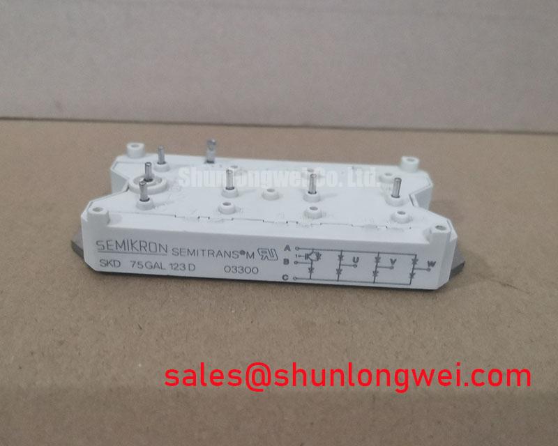
With the DC link discharged and the power connections isolated, compare each marked AC terminal and DC polarity marking against the equipment schematic before taking diode-mode readings. For the Semikron SKD75GAL123D, the core specifications are 1200 V, 75 A, and a Semipont package (Official Specification). Record probe polarity and module temperature alongside each reading so that subsequent comparisons use the same cold-state conditions.
This bridge rectifier module requires a terminal-level assessment, not an assumed gate-drive test. A multimeter reading depends on the connected junction path and the instrument’s test current; it is not a substitute for the manufacturer’s forward-voltage test conditions. 💡 Bench Tip: Disconnect parallel circuit paths before comparing cold-state diode readings, because surrounding components can obscure the module’s response.
Check the surge-current test conditions before comparing a protective fuse with the module’s withstand capability. As a Design Consideration, a sinusoidal 10 ms half-cycle is a specified test waveform only when the applicable manufacturer document defines it that way; it must not become an assumed SKD75GAL123D surge rating. Initial junction temperature, pulse duration, repetition, and reverse-voltage reapplication all affect the interpretation of a surge-current limit.
For fuse coordination, place the module’s documented surge-current and I²t limits beside the fuse manufacturer’s total-clearing data at the prospective fault current and circuit voltage. Distinguish an isolated surge from recurring charging pulses. Repeated events require evaluation of the intervening thermal recovery rather than reuse of a nonrepetitive limit as a continuous operating allowance.
Mechanical inspection belongs in that assessment. Check terminal seating, contact discoloration, heatsink flatness, and the condition of the mounting interface. Apply the model-specific terminal and mounting torque instructions rather than a generic value inferred from bolt size. For model documentation and manufacturer technical resources, use the Semikron-Danfoss official hub.
During replacement evaluation, the SKD145/12 provides a related comparison point, not an established direct replacement. Compatibility requires agreement on circuit configuration, terminal positions, mounting dimensions, thermal conditions, and protection coordination; voltage class or product-family naming alone does not establish interchangeability.
SKD75GAL123D Operational Boundaries: Evaluating Coordination of Primary Spark Gaps and MOV Limits
Trace the incoming surge path from the supply terminals through the installed protection network before assessing stress at the rectifier. The relevant surge-immunity reference is IEC 61000-4-5, not “IEEE 61000-4-5.” It describes equipment-level testing and does not establish a standalone compliance claim for this module.
As a Design Consideration, coordinate any primary spark gap and MOV stage using their sparkover or clamping behavior, impulse-current capability, upstream protection, and connection inductance. The residual voltage reaching the bridge depends on the complete installation. Select and validate protection against the equipment’s supply conditions and applicable surge test, rather than deriving a MOV selection directly from the module’s voltage rating.
An RC snubber addresses a different part of the problem: local ringing and transient voltage across the relevant circuit nodes. Evaluate its placement, dissipation, and effect on measured waveforms under representative loading. Neither a snubber nor an upstream surge protector establishes the module’s terminal-to-baseplate insulation withstand. Inspect creepage paths and contamination separately, and use the applicable insulation-test procedure without treating the semiconductor blocking rating as a dielectric-test voltage.
In a complete power-conversion assembly, the SKD210 can be assessed as a separate rectifier-stage component where the schematic calls for it. Its electrical role and connections must be established independently; it is not an automatic companion to the SKD75GAL123D.
SKD75GAL123D Circuit Protection & Reliability: Assessing Power-Factor Degradation and Harmonic Mitigation
Establish whether the equipment controls its input conversion with a diode bridge or a separately controlled thyristor stage before interpreting firing-angle measurements. A diode bridge has no commanded firing angle. Sweeping an assumed firing angle therefore does not characterize the SKD75GAL123D itself, and negative gate-bias recommendations do not belong in its incoming inspection procedure.
For compatibility assessment in a medium-frequency induction melting or hardening furnace, identify the rectifier position, DC-link arrangement, input reactor, and downstream converter. As an Engineering Recommendation, measure supply current and voltage under representative load to distinguish displacement power factor from distortion-related effects. Interpret harmonics alongside charging-current pulses, supply impedance, and any installed filtering rather than assigning poor power factor to a single module.
The system discussion in The Race for Efficiency offers architectural context, not model-specific lifetime evidence. Likewise, the manufacturer’s MiniSKiiP power-module documentation concerns a separate product family and should not supply SKD75GAL123D mounting limits. Close the inspection record with terminal identification, cold-state readings, mounting checks, and the protection-device references used for the equipment’s acceptance decision.