Content last revised on September 16, 2026
1DI75F-120 Circuit Protection & Reliability: Calibrating High dv/dt Cross-Conduction Shoot-Through
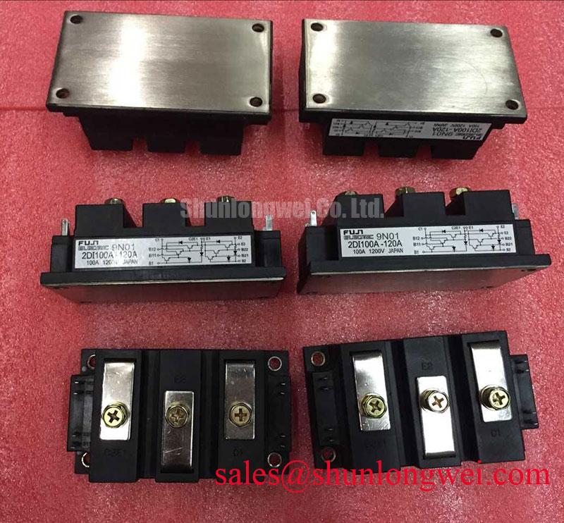
With the drive cabinet isolated and the DC bus confirmed discharged, begin by comparing cold-state terminal resistance readings with the original circuit documentation and inspecting the module terminals, mounting face, busbar contact areas, and gate wiring for mechanical stress. The 1DI75F-120 is a Fuji Electric IGBT module rated at 1200 V collector-emitter voltage and 75 A collector current under the specified conditions, according to the official specification. Its 600 W collector power dissipation rating is specified under datasheet thermal conditions and must be evaluated with the installed heatsink and actual switching duty.
In bridge circuits, a rapid collector-voltage transition can couple through internal capacitances into the opposing gate path. If the inactive device gate rises enough to conduct, cross-conduction can occur. Design Consideration: keep the gate-return route close to its corresponding power-emitter reference, separate it from high-current busbar paths, and inspect for shared gate-return wiring that can introduce unwanted common inductance.
An active Miller clamp and controlled negative gate bias are common system-level approaches where the original driver design requires them. Their voltage levels, clamp threshold, and resistor values must be verified against the existing gate-driver documentation and switching waveforms rather than copied from another converter. Use an isolated differential measurement method to check gate-emitter behavior during the opposite switch transition, then verify collector-emitter overshoot against the DC-link voltage and the module’s official 1200 V VCES rating.
⚠️ Field Alert: Disconnect gate-drive connectors only after stored DC-link energy has been discharged and verified, because an unpowered controller can still retain hazardous capacitor voltage.
For a repair comparison involving a different module family, QM200HA-HK should be reviewed only against the original schematic, terminal arrangement, current demand, gate-drive conditions, insulation requirement, and mechanical fit; it is not a drop-in assumption.
Field Diagnostics & Commissioning: DC-Bus Operating Voltage Headroom Derating in 1DI75F-120 Topologies
Before commissioning, verify the measured DC-bus operating range, regeneration behavior, and transient voltage at the module terminals. The official 1200 V VCES rating provides the device voltage limit, but it does not define a universal converter-bus setting. Engineering Recommendation: reduce the power-loop area, keep DC-link capacitors electrically close to the switching path, and confirm peak collector-emitter voltage during turn-off under the equipment’s real load and temperature conditions.
At elevated installation altitude, environmental reliability assessment should remain a Design Consideration. No model-specific terrestrial-neutron, cosmic-ray, single-event burnout, or FIT-rate data is stated here. Engineers responsible for high-altitude deployment should apply the equipment manufacturer’s environmental qualification requirements and validate DC-bus transient margins through controlled testing rather than infer a failure rate from altitude alone. For a broader technology reference when reviewing 1200 V switching-device behavior in three-phase conversion, see The 1200 V CoolSiC™ MOSFET Advantage in Three-Phase Power Conversion.
A harsh reverse-recovery event in the freewheeling path can create ringing, radiated noise, and additional voltage stress. It may indicate diode behavior, busbar inductance, snubber condition, or gate timing interaction. Check the waveform at the actual module terminals and compare it with a known-good phase where possible. Snubber selection and damping values are system-determined and should be validated against thermal loading and switching results.
In converters that include a separate rectifier or front-end power stage, a module such as 7MBR75U2B060-50 may be relevant to the wider topology review, subject to its own voltage rating, circuit role, and original equipment design.
1DI75F-120 Circuit Protection & Reliability: Calibrating Transient Thermal Impedance
During a heavy pulsed-load investigation, record heatsink temperature, load duration, switching behavior, and protection response before attributing the event to the module. The 600 W collector power dissipation rating is an official specification under its specified thermal conditions, while junction-temperature rise during pulsed operation depends on the time-dependent thermal path, mounting quality, heatsink condition, airflow, and actual electrical losses.
The specified maximum VCE(sat) of 2.5 V under its datasheet test conditions provides a reference for conduction-loss estimation; it is not a universal operating value. For a given on-state current, conduction loss follows the electrical relationship between collector-emitter voltage and current, while RMS current is the relevant current quantity for heating analysis. The underlying RMS concept is described in this Root Mean Square reference. Engineering Recommendation: use measured current waveforms and the original equipment duty cycle when estimating thermal stress, then validate protection timing and case-temperature behavior under controlled conditions.
Where the controller uses desaturation sensing or soft turn-off protection, confirm that the sensing path, blanking logic, and fault latch behavior remain consistent after service. A false trip may result from noise coupling or an altered gate loop, while a missing trip may point to driver, sensing, or interlock faults. Neither condition should be diagnosed from a single static meter reading.
Field Diagnostics & Commissioning: Static and Dynamic Current Distribution in 1DI75F-120 Topologies
When multiple power devices share current, begin with the physical build: compare busbar length, terminal contact condition, gate-loop routing, heatsink flatness, and driver-channel behavior. The positive temperature tendency of IGBT conduction characteristics can assist static current sharing under suitable operating conditions, but it does not guarantee equal dynamic sharing. Dynamic imbalance is strongly influenced by gate-path impedance, wiring symmetry, switching timing, and parasitic inductance.
Design Consideration: use matched physical routing for parallel gate paths and measure each branch with equivalent test placement. A current difference may arise from unequal gate-drive timing, unequal power-loop inductance, thermal gradients, or a mismatch in the surrounding circuit. Verify with synchronized current and voltage measurements instead of relying on apparent similarity between modules.
The official isolation specification for the 1DI75F-120 is 2500 V AC under its specified test conditions. This is an isolation-voltage specification and does not replace the insulation coordination, creepage, clearance, enclosure, or system safety evaluation required for the finished equipment. Product-family documentation can be reviewed through the Fuji Electric Power Semiconductors Portal. For electric material-handling and forklift low-voltage traction repairs, verify the original controller topology, operating bus voltage, driver board compatibility, and thermal interface before returning the vehicle to service.