

Content last revised on November 11, 2026
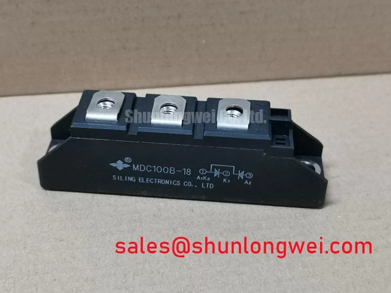
MDC100B-16 Identification and Inspection
- Isolate the power supply, verify stored energy has discharged, and disconnect parallel paths before measuring cold terminal resistance.
- Compare terminal markings with the equipment schematic before reconnecting power conductors or any control wiring.
- Inspect the mounting surface, thermal interface, housing, and terminal hardware for distortion, contamination, or loose connections.
- Record forward and reverse meter readings against the same circuit positions in a known-good assembly, rather than applying a universal pass threshold.
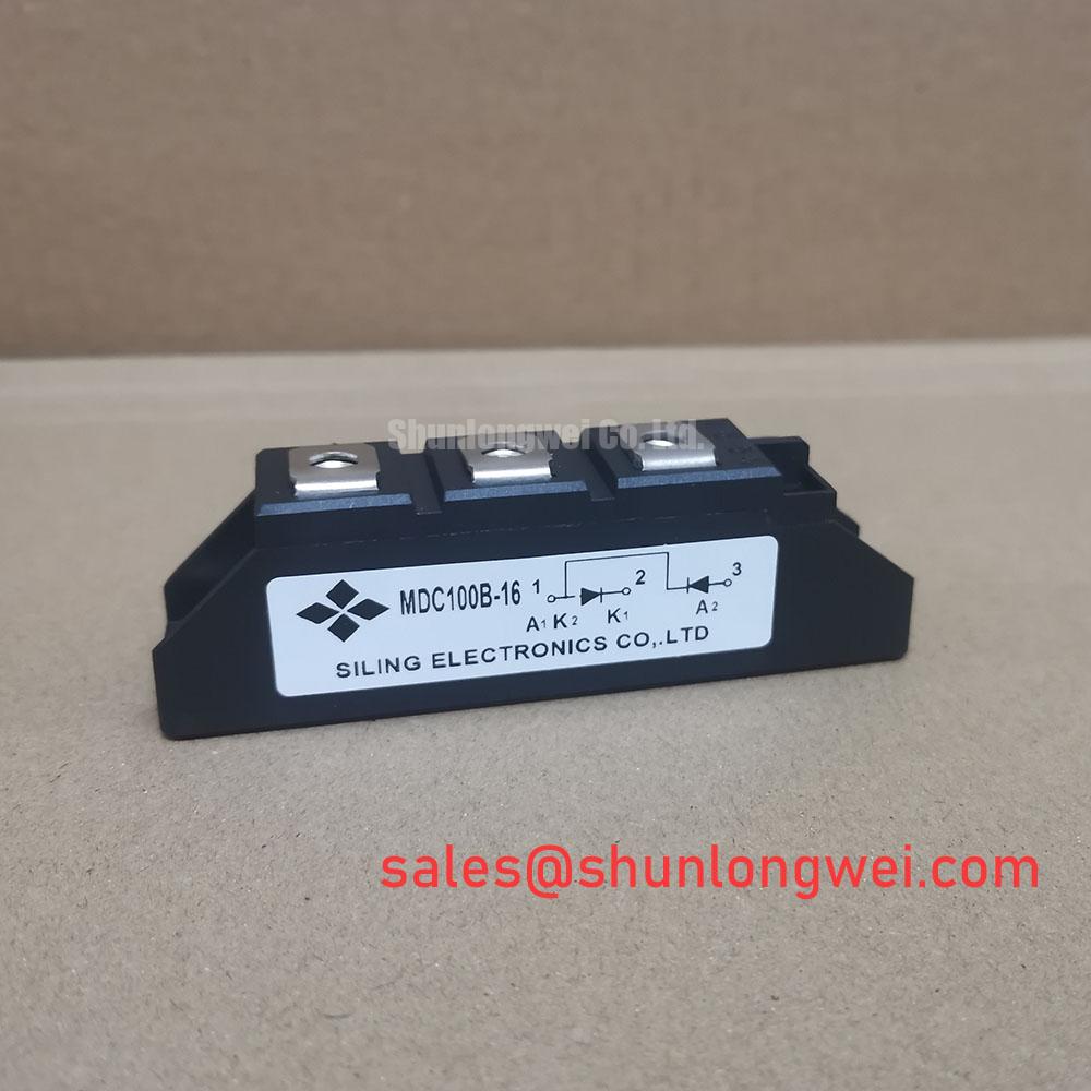
The MDC100B-16 requires an electrical compatibility check as well as a mechanical fit check. The product category is Dual Diode Module, while the supplied configuration field specifies Thyristor / Diode Module. Resolve that distinction through the manufacturer’s circuit diagram before assigning terminal functions or testing a gate circuit. Package appearance alone cannot establish the internal connection arrangement.
| Specification | Product identification baseline |
|---|---|
| Manufacturer | IXYS |
| Part Number | MDC100B-16 |
| Product Category | Dual Diode Module |
| Repetitive Peak Reverse Voltage (VRRM) | 1600.0 V |
| Average On-State Current (IT(AV)) | 100.0 A, subject to the datasheet rating conditions |
| Package | SOT-227B / TO-240AA |
| Configuration / Topology | Thyristor / Diode Module |
| Application-specific verification | Consult Datasheet: circuit diagram, rating conditions, recovery characteristics, surge limits, gate characteristics, mounting torque, and thermal limits. |
MDC100B-16 Circuit Protection & Reliability: Minimizing Commutation Voltage Spikes
Capture the reverse-voltage waveform across the relevant junction during commutation, using a suitably rated differential probe and a measurement arrangement that controls pickup. Design Consideration: reverse recovery can produce a current peak followed by a rapid current transition; circuit inductance can then contribute to voltage overshoot and ringing. Compare recovery peak current and recovery duration only under matching forward-current, temperature, and commutation conditions. Neither a “soft recovery” description nor a recovery-time value should be assigned to this model without its characteristic data.
For an existing RC suppression network, inspect the resistor, capacitor, connections, and routing before changing component values. An altered waveform can reflect a damaged suppression component or changed conductor geometry rather than a defective semiconductor. An Engineering Recommendation is to evaluate suppression against measured switching stress, component heating, and the equipment’s operating envelope; final values belong to the system design.
The explanation of Transient-Voltage-Suppression (TVS) Diodes for Surge Protection provides background on voltage clamping, not evidence that a particular suppressor is suitable here. A TVS device is not automatically interchangeable with an RC snubber. Clamp coordination requires consideration of transient energy, repetitive operation, and the protected circuit’s voltage limits.
During subsystem tracing, treat MDC6005077 as a separate component reference, not an assumed complementary stage. Establish its actual schematic role and electrical interfaces before drawing conclusions about supply or control compatibility.
Assembly Integrity & Layout Architecture: Surge Protection and Thermal Management for MDC100B-16
Match the semiconductor surge-current conditions to the protective fuse’s clearing characteristics before approving a replacement assembly. Design Consideration: a nonrepetitive surge rating is tied to its specified waveform, starting junction temperature, and reverse-voltage conditions after the event. A sinusoidal half-cycle test cannot establish an unrestricted repetitive overload capability, and a reverse-blocking rating does not establish avalanche capability.
Use the equipment protection schedule to compare fuse pre-arcing and total clearing I²t with the semiconductor withstand data under compatible conditions. Prospective fault current and circuit voltage affect that comparison. Replacing a fuse solely by its continuous-current marking can leave the original coordination unresolved; the assessment should retain the specified fuse class and manufacturer coordination information.
Inspect the heatsink contact area for raised edges, embedded debris, or mounting damage. Check that terminal conductors do not impose bending loads on the housing. Field Alert: Apply the documented mounting and terminal torques, and do not use tightening force to pull a distorted module onto the heatsink. Thermal-interface application should follow the assembly instructions rather than an assumed universal thickness.
The packaging application guide offers packaging context for examining interconnection geometry; it does not provide model-specific endurance certification. When comparing MDC250C-16, check the circuit arrangement, terminal layout, mounting drawing, thermal characteristics, and protection coordination independently. A related designation does not establish interchangeability.
MDC100B-16 Circuit Protection & Reliability: Verifying Thyristor Triggering Requirements
Identify a documented gate and cathode connection before attaching a trigger tester. For a confirmed thyristor section, inspect the complete firing path, including connectors, pulse delivery, and the cathode return. Design Consideration: inadequate triggering can restrict initial conduction, but gate-pulse amplitude, rise time, duration, and repetition must follow the actual device requirements and controller design.
Compare IGT and VGT under their stated test conditions, then examine the delivered pulse at the device terminals rather than only at the controller output. Extended pulses or pulse trains require coordination with latching and holding behavior. A cold resistance reading can reveal an abnormal connection, but it cannot certify trigger performance or identify the cause of damage by itself.
When evaluating a medium-frequency induction melting or hardening furnace power supply, verify whether the proposed position is a controlled rectifier stage rather than assuming suitability for the high-frequency switching stage. In phase-controlled rectification, firing angle affects conduction intervals and input-current harmonics. Engineers should assess trigger synchronization, load-current continuity, and existing harmonic-control provisions together, then verify stable firing throughout the equipment’s permitted operating range.