

Content last revised on September 10, 2026
VESA and JEIDA Data Mapping Alignment for G220SW01 V0 Signal Checks
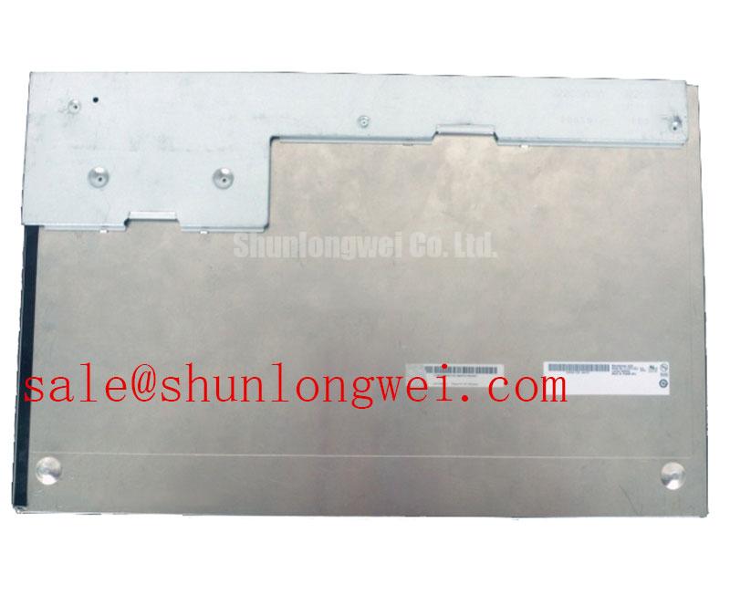
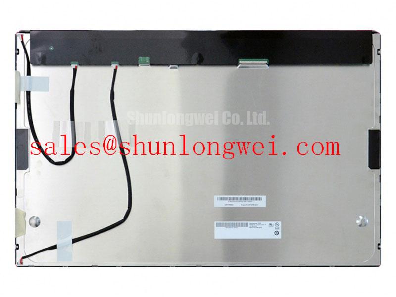
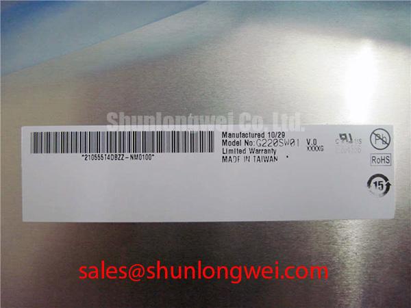
Begin a G220SW01 V0 fault inspection with power removed, then inspect the display cable, connector latch, contact condition, and cable routing before replacing the LCD module. The official factory identification confirms an AUO TFT LCD Display Module in the Industrial Grade LCD/HMI Panel category. This verifies the product identity, but the required interface voltage, connector assignment, timing table, optical characteristics, and backlight requirements must be checked against the original equipment documentation before installation.
A black screen with an apparently active machine controller can originate from several locations: the panel power rail, the host display transmitter, a partially seated signal connector, a damaged cable, or the illumination system. A visible image under external light may suggest that image data is reaching the panel while illumination needs separate investigation. A fully blank surface does not establish a single fault cause; compare the panel connection and signal path with a known working assembly where available.
VESA and JEIDA refer to different digital color data mapping conventions. If a replacement display is connected to a transmitter configured for the opposite mapping, the result can include abnormal colors, split image regions, banding, or unreadable graphics. These symptoms should be treated as a mapping and signal integrity investigation, not as conclusive evidence of a defective display. The system integrator should verify the original transmitter configuration, interface documentation, cable pinout, clock polarity, and data mapping requirement before applying power.
Design Consideration: Differential display links depend on controlled routing, sound cable termination, and a stable reference path. Excessive cable strain, poor shielding continuity, or a connector that is not fully engaged can degrade signal quality and produce intermittent image faults. Oscilloscope assessment against a known good signal path can help distinguish a host output problem from an interface problem.
For a same class comparison during compatibility review, the LMS700KF01-001 can be examined as a separate reference item. It is not an automatic replacement for the G220SW01 V0. Mechanical fit, electrical interface, mapping, illumination arrangement, and controller timing remain system determined checks.
⚠️ Field Alert: Disconnect system power and allow stored energy to discharge before reseating any display connector, because live insertion can expose signal pins to uncontrolled voltage differences.
Chassis Mounting Pressure and Optical Surface Inspection
Before fitting the AUO G220SW01 V0 into a CNC operator panel or robot teach pendant, inspect the bezel opening, support points, retaining brackets, and cable exit path. The factory supplied identification does not establish a mounting torque, dimensional envelope, or bezel tolerance in the available product information. Those values must come from the original panel drawing or the host equipment service documentation.
Design Consideration: Uneven mounting pressure can influence the visible appearance of an LCD assembly. Localized brightness variation, pressure marks, or dark areas may be associated with enclosure distortion, a warped bracket, uneven fastener loading, or contact with nearby components. These observations are diagnostic clues rather than proof of one specific mechanism. Inspect the panel both before and after final fastening, using a uniform image from the host system where practical.
Use a cross pattern when tightening multiple retaining points so the chassis load is introduced gradually and evenly. The final fastening method is determined by the host enclosure material, bracket design, thread engagement, and the equipment manufacturer’s service procedure. Avoid treating a generic fastener torque value as an official requirement for this AUO module.
Text flicker, visible brightness stepping, or audible noise near the display enclosure requires a broader inspection. The source may involve the system backlight driver, the display controller, power supply ripple, grounding, cable routing, or the host software brightness command. The G220SW01 V0 should be evaluated with the original illumination and control architecture documented by the equipment maker rather than with assumed dimming characteristics.
Where a machine uses a separate display related subsystem, the LQ9D03B is a relevant item to review within a wider service assessment. Its presence in a system does not confirm electrical compatibility with the G220SW01 V0; the technician should compare connector functions, supply requirements, and control behavior at the equipment level.
Humidity Storage, Temperature Exposure, and Interface Stability Checks
Inspect the G220SW01 V0 packaging condition and display surface before installation, especially after unknown storage or transport exposure. Moisture marks, corrosion around external contacts, residue, damaged seals on the host enclosure, or cable contamination justify a controlled inspection before the module is energized. The official product information identifies the item as an industrial LCD/HMI panel, but it does not provide verified storage humidity limits, operating temperature limits, response time, or environmental qualification values in the supplied factory parameter set.
Design Consideration: Low temperature can change the apparent update behavior of liquid crystal displays, while condensation and elevated humidity can affect the larger display assembly, connectors, cable interfaces, and surrounding electronics. The correct response is to stabilize the equipment under its specified service conditions, inspect for moisture ingress, and compare image behavior against documented system requirements. Do not assign a field symptom to a temperature related panel defect without checking the controller, cabling, and illumination supply.
Signal stability across the machine’s intended operating conditions depends on the host transmitter, cable assembly, grounding, connector retention, and the display interface requirements. If artifacts appear only after warm up or only at cold start, capture the host supply condition and image output at the moment of failure. This provides a more useful service record than assuming a fixed relationship between temperature and panel response.
Engineers assessing industrial HMI repair practices, enclosure exposure, and display integration checks can use Industrial Display & HMI Solutions as a practical reference. It should support, not replace, the original machine documentation and panel level specifications.
Power conversion noise can also enter an HMI system through shared supplies or grounding paths. For broader technical reading on power electronics topics that may affect adjacent system boards, consult IEEE Transactions on Power Electronics. Such system level references do not define the specifications of this LCD module.
Backlight Supply Isolation and High Voltage Safety Assessment
When the G220SW01 V0 shows a faint image, intermittent illumination, or a screen that changes with cable movement, isolate the display data path from the host illumination path during diagnosis. The available official factory information confirms the product category and module identity, but it does not confirm the internal backlight technology, lamp count, LED arrangement, input current, dimming method, or ignition requirement. The system integrator should verify the required supply and backlight interface from the original panel documentation.
Do not assume that a display module uses a particular driver topology based on its appearance or equipment age. A host system may contain separate backlight circuitry, integrated display power conditioning, or a dedicated controller board. Examine the machine schematic, service manual, and existing cable labels before applying test equipment. If the original assembly includes a high voltage section, use appropriate insulated probes and follow the equipment manufacturer’s lockout procedure.
Design Consideration: Audible noise around a display enclosure can arise from several energized assemblies, including power conversion hardware, mechanical brackets, or vibration coupling from nearby equipment. First determine whether the noise follows brightness control, panel power state, machine load, or physical pressure on the enclosure. This avoids replacing a display module when the root cause lies elsewhere in the HMI power path.
For industrial automation CNC operator panels and robot teach pendants, replacement evaluation should remain disciplined: verify the exact G220SW01 V0 marking, compare the host connector and mechanical interface with the removed unit, confirm the required electrical documentation, and inspect image behavior only after the module is correctly secured. The panel is a factory verified AUO TFT LCD Display Module; final suitability remains dependent on the original equipment configuration.