Content last revised on September 10, 2026
Digital RGB Interface and Logic Power Rail Verification
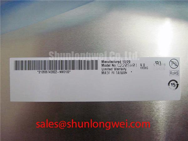
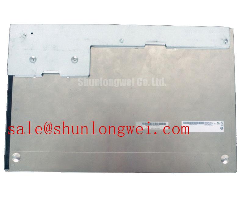
| Manufacturer | AUO |
|---|---|
| Product Model | G220SVN01-1 |
| Product Category | LCD Display |
| Screen Diagonal | 22.0 inch or 558.8 mm |
| Active Resolution | 1680 × 1050 WSXGA+ |
| Pixel Density | 90.2 PPI |
| Luminance | 250 cd/m² |
| Contrast Ratio | 2000:1 |
| Viewing Angles | 89°/89°/89°/89° typical |
| Logic Supply | 5.0 V typical |
Probe the panel logic rail at the display connector while the host controller starts, then compare the observed supply against the required 5.0 V typical VDD specification for G220SVN01-1. A rail that rises cleanly but collapses when the video source begins transmitting can point toward cable loading, connector contamination, or an upstream regulator issue. A rail that remains stable while the image intermittently tears, shifts, or divides requires signal-path investigation rather than immediate panel replacement.
The official electrical information establishes a 5.0 V typical logic supply. It does not establish a 3.3 V logic rail, a TTL 24-bit RGB pinout, an LVDS interface, differential-pair impedance, or JEIDA and VESA mapping for this specific model. Those interface details must be matched against the original equipment schematic, connector drawing, and panel documentation before connecting a replacement display. Applying assumptions from another panel family can create persistent image corruption or prevent the display from initializing.
Engineering Recommendation: Capture the timing and data activity from the known-good host signal path when possible, with the original cable and display assembly retained as the reference. Compare enable sequencing, synchronization behavior, and color-channel activity under the same machine state. If a radar or navigation console presents a stable backlight but no usable image, isolate the host output and interconnect before attributing the symptom to the LCD glass.
The 1680 × 1050 active resolution provides a 16:10 workspace suitable for layouts that need simultaneous plotting, status fields, and operational information. Its 90.2 PPI density supports clear rendering of fine graphical elements when the controller outputs the native format. Scaling an incompatible source format can introduce softness, clipping, or incorrect aspect ratio that is not evidence of a panel fault.
For display-system background relevant to harsh industrial interfaces, consult AUO’s Industrial Display and Embedded Systems information. This reference supports broader system evaluation, while the actual connector, timing, and power sequence remain equipment-specific integration items.
Surface Optical Performance and High-Ambient Readability
Inspect the powered screen under the actual site lighting angle, then compare a dark image, a mid-gray image, and a white image while changing the observer position across the panel. The official viewing-angle specification is 89°/89°/89°/89° typical, representing a symmetric 178° viewing envelope. Uneven brightness, apparent color shift, or a localized haze observed during this check can arise from the panel, the cover window, surface contamination, or optical interaction with the enclosure.
The official optical ratings are 250 cd/m² luminance and 2000:1 contrast ratio. These are panel specifications, not confirmed outdoor readability ratings under a stated lux level. The available specifications also do not confirm an anti-glare etch, anti-reflective coating, sunlight-readable enhancement, or a defined optical-bonding stack. Do not treat a contrast result measured in a controlled condition as proof of readability under direct ambient light.
Design Consideration: In navigation bridge consoles and other high-ambient installations, evaluate the complete visual stack rather than the LCD alone. The cover lens condition, gasket seating, enclosure depth, display angle, and incident reflections can materially affect perceived contrast. A clean, controlled comparison against a known-good assembly is more useful than judging the panel from a single viewing angle.
Cold environments can affect display response visually, but no low-temperature operating range, response-time specification, heater provision, or heater-control requirement is established here for G220SVN01-1. If motion appears sluggish during a cold start, allow the equipment to reach its intended enclosure condition and assess it again with stable input timing. The system integrator should verify the permissible environmental range from the original panel documentation and equipment-level validation records.
⚠️ Maintenance Note: Inspect the perimeter gasket, enclosure drain paths, and cooling airflow during scheduled service because trapped moisture or dust around the display stack can degrade long-term optical uniformity.
Mechanical Stress and Glass Substrate Damage Prevention
Display full red, green, blue, black, and white test fields immediately after reassembly, then inspect for fixed lines, color-specific defects, edge brightening, or pressure-sensitive changes while the enclosure remains stationary. This practical sequence separates source-image issues from display symptoms without placing additional flex stress on the panel. A defect that remains in the same screen location across all test images deserves comparison with the original display and cable assembly.
Use a flashlight at an oblique angle only to inspect the external surface, cover lens, frame condition, and signs of uneven mechanical loading. A dark region may relate to backlight performance, optical layers, a cover-window shadow, or a display-side condition; it should not be assigned to an internal driver or glass structure without controlled evidence. The supplied specifications do not define internal driver-bump construction, glass-substrate architecture, or approved frame torque.
Design Consideration: Seat the panel evenly in its mounting aperture and avoid forcing a frame into a distorted opening. Mechanical twist can produce visual non-uniformity that changes with enclosure pressure, while an overtightened bezel can create local stress near the edges. The applicable fastener type, torque, support points, and compression limit must be determined by the host equipment drawing rather than inferred from the display model.
Signal routing should be evaluated as part of the assembly when a display fault appears after cable replacement or cabinet work. The official data provided for this model does not define differential signaling, a controlled-impedance requirement, a skew budget, or an EMI rating. Where the host design uses high-speed links, retain its original routing rules and verify the waveform against a known-good signal path. This avoids imposing an interface standard that may not belong to the installed panel.
When assessing a different display for an older equipment repair, LQ10D321 can be reviewed as a separate sourcing candidate. Its mechanical dimensions, active area, interface, power arrangement, and timing must be independently checked; it is not established here as a direct replacement for the 22.0 inch G220SVN01-1.
Cold-Start Display Response and Environmental Evaluation
Run a controlled moving-gray image after cold startup and observe the panel again after the enclosure has stabilized, keeping the input source, cable position, and brightness setting unchanged. If trailing, delayed transitions, or intermittent visual artifacts improve with stable environmental conditions, record that behavior alongside the measured logic rail and source output. This disciplined comparison prevents a temperature-related observation from being confused with a fixed data-path defect.
No gray-to-gray response-time value, operating-temperature range, storage-temperature range, heater-strip feature, perimeter-seal construction, or thermal-cycle rating is specified in the official data supplied for G220SVN01-1. Claims about operation at sub-zero temperatures or survival across a defined thermal range therefore cannot be made for this display. The system integrator should verify the required environmental limits from the original panel documentation and the equipment manufacturer’s records.
Engineering Recommendation: For equipment exposed to condensation risk, inspect the enclosure sealing strategy, cable-entry condition, and airflow path before fitting a replacement display. Use gradual stabilization of the complete equipment assembly where operating procedures permit, since abrupt application of power to a moisture-affected console can complicate diagnosis. Test with native 1680 × 1050 output after the enclosure condition is stable, then compare contrast and viewing consistency using the specified 250 cd/m², 2000:1, and symmetric viewing-angle characteristics as the relevant panel reference points.
For practical inspection methods involving sealing, installation environment, and industrial HMI maintenance, see Industrial Display & HMI Solutions. For potential use in marine radar or navigation bridge equipment, engineers should evaluate enclosure sealing, salt exposure controls, electrical interface compatibility, and equipment-specific environmental requirements as a complete assembly.