




Content last revised on September 10, 2026
Sharp LQ10D346 Replacement Inspection
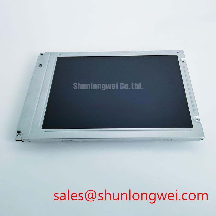
Before energizing a replacement Sharp LQ10D346, inspect the TFT LCD display module for enclosure damage, connector displacement, visible contamination, and uneven frame pressure, then compare its identification data with the equipment service record. The available factory information identifies this unit as an industrial grade LCD/HMI panel manufactured by Sharp, with a TFT LCD display module construction. The supplied product record marks its specification status as Official Factory Spec Verified. Electrical interface, optical, dimensional, backlight, and environmental values should be confirmed against the original panel documentation before installation.
High Voltage Backlight Testing and Secondary Coil Insulation Verification
Backlight architecture is a critical replacement checkpoint for the LQ10D346 because the available factory data supplied for this product does not state whether the installed illumination system uses a particular lamp or LED arrangement. The system integrator should verify the original panel documentation, backlight connector, driver topology, ignition behavior, and required supply conditions before connecting a replacement module. Do not infer the backlight type from the external panel appearance alone.
Where the original assembly uses a high voltage cold ignition circuit, maintenance personnel should isolate the secondary circuit and follow the equipment manufacturer’s approved insulation test procedure. The test voltage, ramp rate, discharge time, probe category, and acceptance criteria are system and safety procedure requirements, not confirmed factory parameters for the LQ10D346. A replacement display should not be connected to an unverified inverter because abnormal transformer loading, open lamp detection, or incompatible feedback behavior may produce intermittent illumination or audible electrical noise.
Where the host system uses a constant current LED driver, engineers should verify the driver’s output range, enable logic, dimming method, current regulation, and fault response against the original display assembly. A PWM dimming ratio, operating current, or brightness lifetime value is not stated in the supplied LQ10D346 factory parameter set and should not be assigned to this model without the applicable Sharp documentation. The practical objective is to confirm that the driver reaches a stable operating state without excessive ripple, acoustic excitation, repeated restart, or uneven screen illumination.
Cold environment testing deserves particular attention in equipment that may be installed near outdoor process areas or temperature controlled cabinets. Liquid crystal response can change as temperature falls, while a separate backlight driver may have its own startup behavior. A slow image transition, temporary brightness variation, or delayed display activation should therefore be assessed by checking the panel supply sequence, display enable signal, backlight enable signal, and video source timing as a group. If a heater strip or cabinet heater is part of the host design, its control logic must be evaluated by the system engineer rather than assumed to be part of the Sharp display module.
For a potential hazardous petrochemical Zone 2 operator station, the LQ10D346 may be evaluated as a replacement display within a certified enclosure assembly, subject to complete system approval. The display module itself should not be described as independently explosion proof or independently certified for a hazardous location. The enclosure, cable glands, operator controls, thermal management, bonding, and installation method must be assessed as one complete system.
Preventing Frame Pressure and Localized Optical Mura
When fitting the LQ10D346 into a replacement bezel, begin with a dry mechanical trial. Check that the panel rests evenly on its intended support surfaces and that the frame does not contact active display areas, flexible circuits, or connector housings. The supplied official product data confirms the TFT LCD display module category but does not provide a dimensional drawing, bezel envelope, mounting hole pattern, or fastening torque. Those values must be taken from the original Sharp mechanical documentation or measured from the approved host assembly.
Uneven fastening can place local stress on the display stack. On a dark image, this may appear as localized brightness variation, pressure marks, or optical mura. Such symptoms do not establish a single cause, so the technician should compare the screen before and after each mechanical adjustment. A useful inspection sequence is to remove unnecessary frame loading, verify support contact, inspect gasket compression, and repeat the same dark field test at a controlled viewing angle.
Cross-pattern tightening is a general installation consideration when a display is retained by several fasteners, but the correct torque remains dependent on the chassis, insert material, washer arrangement, and manufacturer instructions. The LQ10D346 factory information supplied here does not specify an M3 or M5 tightening value. Use the approved mechanical drawing rather than transferring a torque value from another LCD model. Fasteners should secure the display without bending the bezel or compressing the panel unevenly.
Gasket selection also affects mechanical loading. A sealing strip that is too thick may create localized pressure, while a discontinuous gasket may allow dust ingress or vibration movement. The replacement procedure should record the original gasket position, contact width, corner treatment, and cable exit arrangement. If the original panel used optical bonding, perimeter sealing, or a separate protective window, these features should be verified from the equipment design. They should not be assumed from the LQ10D346 model designation.
Video integrity must be checked separately from mechanical fit. The supplied information does not confirm the LQ10D346 interface type, differential pair assignment, signal impedance, pixel timing, or skew tolerance. The system integrator should verify the required interface from the original panel documentation and compare the host controller configuration before powering the display. If image noise appears in a high EMI factory environment, inspect cable routing, shield termination, connector seating, grounding topology, and the known good signal path. An oscilloscope or suitable interface analyzer can help distinguish a source timing issue from a cable or connector problem.
For comparison work, engineers assessing display options by size or resolution can review the independently listed LM190E08 TLG6. That reference should be treated as a separate model for compatibility evaluation, not as an automatic substitute for the LQ10D346. Physical dimensions, electrical interface, optical behavior, mounting geometry, and host firmware must be matched before any replacement decision.
Thermal Cycling, Polarizer Protection, and Gasket Integrity
Installers should inspect the full perimeter of the LQ10D346 mounting area before exposing the display to repeated temperature changes. Look for gasket discontinuity, trapped debris, frame distortion, cable pinch points, and areas where the bezel may rub against the display. The available official product record does not provide a qualified operating temperature range, storage temperature range, humidity limit, sealant formulation, polarizer adhesive rating, or thermal cycle test result. These limits must be confirmed through the original Sharp documentation and the equipment qualification plan.
Cold starts can produce slower liquid crystal response and temporary image lag, but the correct diagnosis requires controlled measurement. Record the panel temperature, host supply behavior, video timing, backlight state, and time required for the image to stabilize. If a display appears white, dim, or incomplete during startup, review power sequencing and enable timing rather than assigning the condition to the panel alone. The host controller may require a defined order for logic power, video signals, display enable, and backlight enable.
Power removal should also be assessed. Residual charge in the host circuit or a delayed disable signal can leave a temporary image or backlight condition after shutdown. The system engineer should verify discharge behavior and confirm that the host power rails fall within the limits stated in the original panel documentation. Do not insert or remove the display cable while energized, because connector contact sequencing can expose the module and controller to unintended electrical conditions.
Direct sunlight and high ambient illumination can make a healthy panel appear to have weak contrast. The supplied LQ10D346 information does not state a contrast ratio, luminance value, anti glare coating, surface reflectivity, or sunlight readability rating. Optical acceptance testing should therefore use the original equipment specification, the same protective window, and the same ambient lighting arrangement. If a front cover or viewing filter is installed, its effect on reflection, haze, heat absorption, and touch operation should be measured as part of the complete HMI assembly.
Thermal expansion between the display frame, cabinet, gasket, and protective window should be allowed for in the mechanical design. The aim is to preserve uniform support while avoiding permanent edge loading during temperature changes. Designers should verify the enclosure’s condensation control, ventilation path, and pressure equalization strategy where applicable. A sealed enclosure can protect against dust and moisture only when its gasket condition, cable entries, service access, and installation workmanship are all maintained.
Maintenance Note: Inspect the cooling path, perimeter gasket, frame fasteners, and display cable lock during scheduled cabinet service, with power isolated before any connector work.
Backlight Consistency and Lifetime Data Verification
Brightness stability for the LQ10D346 must be evaluated using confirmed factory data rather than a generic LCD lifetime assumption. The supplied specification set identifies the unit as a Sharp TFT LCD display module but does not state backlight technology, rated luminance, current, dimming range, L70 or B50 life, or MTBF. Any procurement comparison that depends on a claimed half life should request the applicable Sharp datasheet or qualification document and confirm its test conditions.
During bench inspection, measure brightness across the active image area after the display has reached a stable operating condition. Compare the center and edge regions, then repeat the test with the same video pattern and backlight setting used by the host equipment. A brightness difference may involve the display, driver regulation, optical stack, protective window, temperature, or measurement geometry. The result should be recorded as an assembly observation rather than treated as proof of a particular internal material failure.
Thermal management is a design consideration for any enclosed HMI. Heat from the display, backlight driver, controller, and nearby power electronics can accumulate around narrow cabinet edges. The system designer should provide an effective heat path while preserving gasket compression and avoiding direct mechanical loading on the panel. Rail dimensions, spreader materials, interface compounds, and airflow should be selected from the cabinet thermal model and then verified by temperature measurement under actual operating duty.
Static industrial screens should be checked for retained image behavior during qualification. A fixed alarm page, process trend, or status bar displayed for long periods can create uneven aging in some display technologies, but the supplied LQ10D346 factory parameters do not define an image retention limit or required screen saver interval. If the host application permits, maintenance teams can evaluate periodic screen content variation, reduced static brightness, or controlled standby operation according to the equipment’s functional and safety requirements.
For field troubleshooting, compare the LQ10D346 with a known good display or a known good controller while changing only one condition at a time. Verify the supply at the display connector, inspect enable and video activity, check the cable lock, and document the result at the same temperature and brightness setting. This approach avoids treating a blank screen, flicker, uneven illumination, or slow response as a single-cause fault without measurement.
Engineers developing a broader replacement or retrofit plan can consult Industrial Display and HMI Solutions for system-level considerations covering enclosure integration, environmental protection, and service evaluation. Any final selection involving the Sharp LQ10D346 should remain tied to verified dimensions, interface requirements, optical expectations, environmental limits, and the certification requirements of the finished operator station.