

Content last revised on September 5, 2026
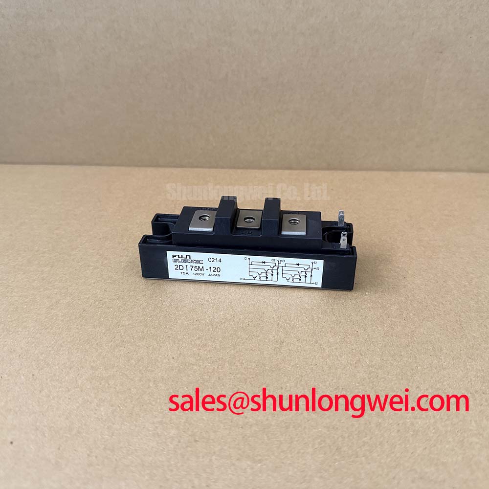
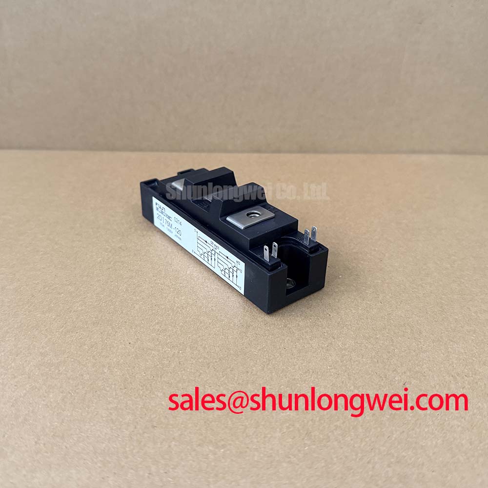
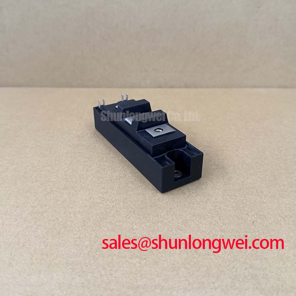
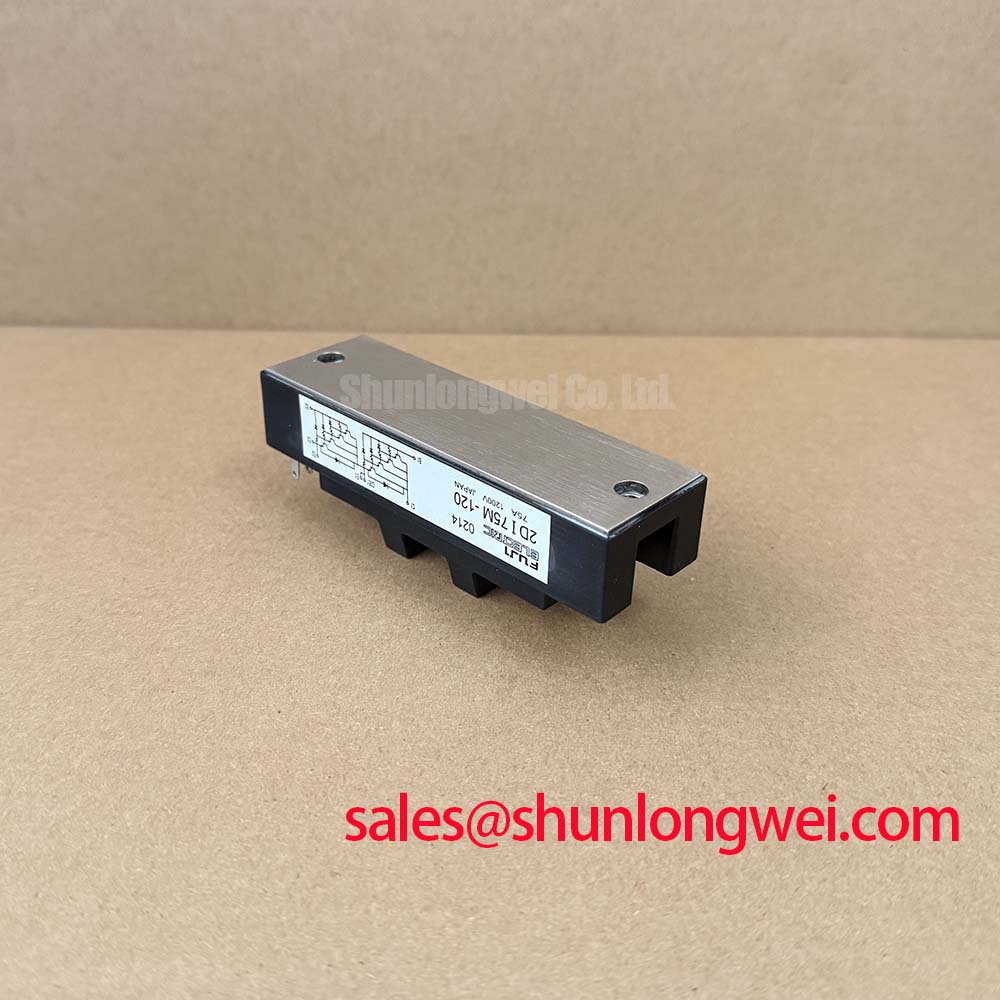
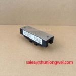
2DI75M-120 Fuji Electric 1200 V 75 A Diode Module
With the soft starter fully isolated, first inspect the 2DI75M-120 body, terminal hardware, and copper baseplate, then compare cold terminal impedance with a known good reference before applying high voltage. A cold test can reveal an unexpected short or open condition, but it cannot replace a controlled powered test or the original Fuji Electric documentation for terminal identification.
| Parameter | Rating | Engineering Context |
|---|---|---|
| Repetitive Peak Reverse Voltage, VRRM | 1200 V | Maximum stated reverse blocking voltage under the specified conditions |
| Forward Current, IF | 75 A at TC = 25°C | Rated forward current under the stated case temperature condition |
| Power Dissipation, PC | 500 W | Specified power dissipation value for thermal evaluation |
| Isolation Voltage, VIsol | 2500 V AC | Isolation between terminals and the copper baseplate |
| Pulse Current | 150 A for 1 ms | Specified pulse-current condition; it should not be treated as a general surge-current rating |
| Operating Junction Temperature, Tj | +150°C | Upper stated junction operating limit |
| Storage Temperature, Tstg | −40°C to +125°C | Permitted non-operating storage range |
2DI75M-120 Thermal Electrical Optimization: Coordination of Primary Spark Gaps, MOVs, Practical Tuning
For a high voltage three-phase motor solid-state soft starter, the protection network must be evaluated as a complete power assembly rather than as an isolated diode module. The 1200 V VRRM rating defines the stated reverse-blocking boundary, while the 150 A for 1 ms rating describes a limited pulse condition. Neither value is a substitute for a system surge study, fuse coordination review, or transient measurement.
A Design Consideration is to place surge-limiting elements and RC suppression stages according to the starter topology, line voltage, prospective fault current, and switching waveform. Primary spark gaps and MOVs require voltage and energy coordination so that their intervention does not create a damaging residual impulse across the semiconductor. The system designer should verify the actual clamping voltage at the module terminals during an IEC 61000-4-5-related test where that standard applies to the complete equipment.
The supplied product data does not include a fuse I2t coordination table, terminal torque value, package dimensions, or a detailed terminal drawing. These items must be taken from the applicable Fuji Electric documentation before selecting a semiconductor fuse or tightening field wiring. Keep the high-current loop compact and route sensing or control wiring away from the commutation path to reduce common-mode ground bounce. General power semiconductor operating principles can be reviewed in this power semiconductor device reference.
2DI75M-120 Operational Boundaries: Evaluating Phase Angle Voltage Profiling and Current Limits
During a replacement assessment, confirm that the original starter uses this device in a compatible rectification or freewheeling position. The provided data identifies the unit through voltage, current, dissipation, isolation, pulse-current, and temperature ratings; it does not define a complete phase-angle control profile. Claims about reducing locked-rotor current from a specific multiple to another value therefore belong to system validation, not to the module specification.
As an Engineering Recommendation, the control team should monitor line current, terminal voltage, motor acceleration, and device case temperature while adjusting the associated control or switching sequence. The electrical stress depends on motor rating, supply impedance, bypass contactor timing, load torque, and the protection network. A replacement should be accepted only after the measured peak voltage and current remain within the applicable equipment design limits.
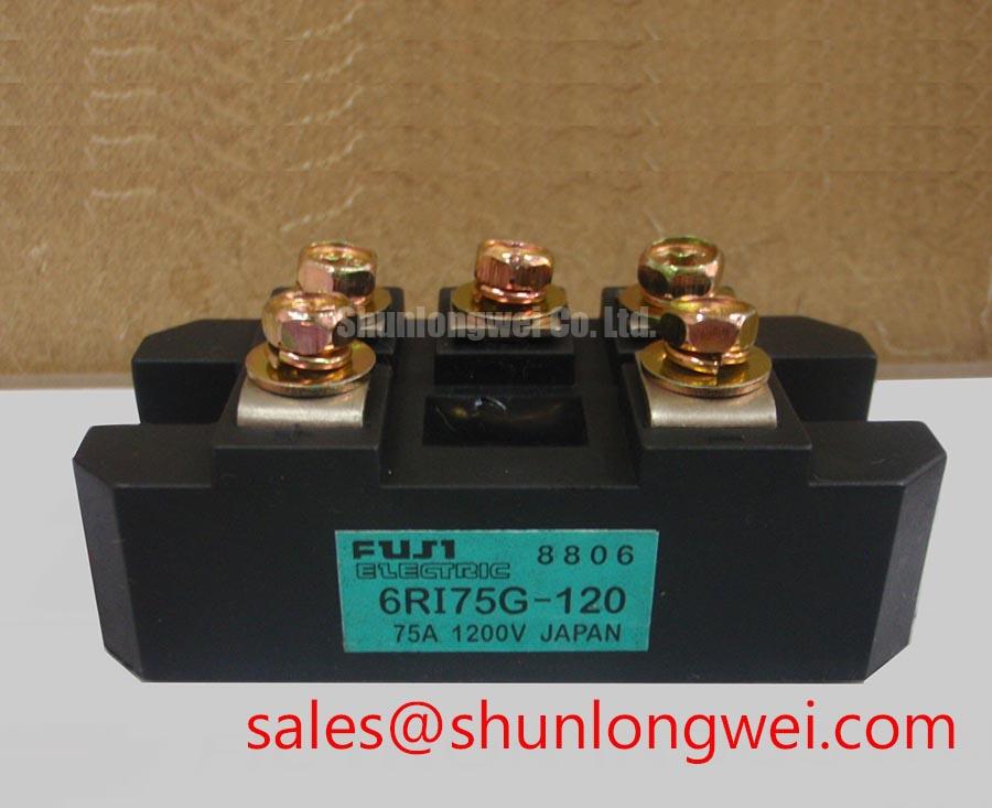
Check the driver and protection supply arrangement separately. Where the soft starter includes an upstream rectifier or related power stage, engineers may evaluate the associated 6RI75G-160B as a separate component in the system topology. It should not be treated as an automatic substitute or guaranteed companion for the 2DI75M-120.
Assembly Integrity and Layout Architecture: Implementing Thermal and Layout Margins during High Peak Current
Before installation, inspect the baseplate for distortion, contamination, and evidence of uneven contact. The published 500 W PC value and +150°C Tj limit make the thermal path a central verification point. Designers should establish the required heatsink, interface material, airflow, and enclosure conditions from measured losses and the real duty cycle. The supplied parameter set does not state an IFSM sinusoidal 10 ms half-cycle surge rating, so that value must not be inferred from the 150 A pulse-current rating.
Terminal connections should follow the original mechanical drawing and conductor arrangement. Minimize stray inductance in the high-current path to control switching overshoot, then verify the peak waveform with an oscilloscope and a suitable differential probe. The 2500 V AC isolation value applies to the stated terminal-to-copper-baseplate isolation condition; creepage, clearance, pollution level, enclosure geometry, and working voltage still require a complete equipment assessment.
⚠️ Field Alert: Isolate and discharge the equipment before inserting or removing wiring, and use the fast-fuse manufacturer’s verified I2t data rather than assuming the module pulse rating will clear a dead short.
Do not apply an SMT reflow profile to this power module unless the manufacturer’s package documentation explicitly permits that process; general reflow background is available in this SMT reference.
2DI75M-120 Operational Boundaries: Evaluating AC-to-DC Transfer Characteristics across Voltage Limits
When reviewing AC-to-DC transfer behavior in a power stage that includes this diode module, record the actual line waveform, control command, load current, and commutation condition rather than relying on nominal angle labels alone. A theoretical sweep from zero to 150 degrees can help frame a control study for an associated controlled stage, but the resulting average output, power factor, and reactive power depend on the circuit topology and load. Those characteristics are not factory ratings supplied for the 2DI75M-120.
Verify voltage stress during the complete operating range against the 1200 V VRRM boundary, and check current heating against the 75 A IF rating at the stated case condition. The control engineer should also examine dead time, noise immunity, and common-mode return paths in any associated switching stage. If the measured signal is unstable, compare it with the known-good phase and inspect cable routing, shielding, reference bonding, and probe technique before assigning a component fault.
For broader layout, protection, and reliability context, consult the Power Electronics Masterclass. The 2DI200MC-050 may also be reviewed as a separate replacement candidate when its voltage, current, package, terminal arrangement, and thermal requirements have been matched against the original assembly.