Content last revised on September 21, 2026
Assembly Integrity & Layout Architecture: RC Snubber Network Review for 2DI75M-050
Confirm that the installed bridge is the 2DI75M-050 and that applied operating conditions and voltage transients remain within its 500 V specified voltage rating. In rectifier assemblies, RC snubbers and series reactors are system level parts rather than inherent features of this diode module. Their suitability depends on transformer leakage inductance, cable routing, load commutation, incoming waveform, and measured switching transients.
Design Consideration: keep the current path from AC input through the bridge and DC link physically compact where the equipment layout allows. This reduces parasitic inductance that can create voltage ringing during current transfer. Where an existing RC network is fitted, retain the original topology during emergency repair unless waveform measurements and the system schematic support a controlled redesign. A changed capacitor or resistor value can shift the transient response instead of solving the underlying layout, load, or supply issue.
Inspect all terminal interfaces for uneven contact pressure, oxidized conductors, and signs of local heating. The module mounting surface and heat sink should be clean and flat, with thermal interface material applied evenly according to the equipment service procedure. ⚠️ Field Alert: Isolate all energy sources and verify stored DC link energy is discharged before loosening bridge terminals or mounting hardware.
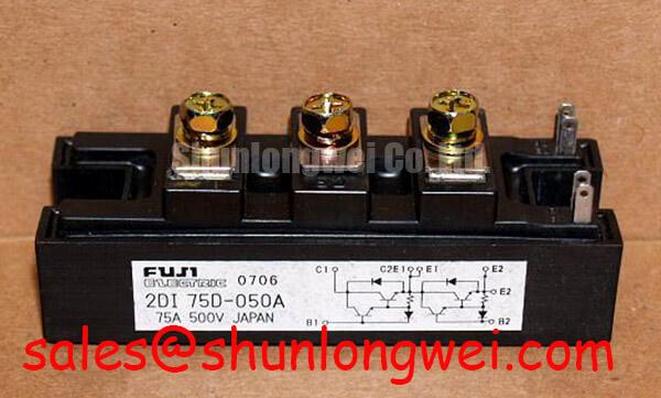
For comparison of mechanical and electrical fit within a Fuji Electric diode module repair assessment, engineers can review the 2DI75A-140 separately; its designation does not establish direct replacement compatibility, which must be confirmed against the original circuit, terminal arrangement, voltage rating, and thermal design.
2DI75M-050 Circuit Protection & Reliability: Reviewing Surge Current Coordination
The 75 A current rating is an Official Specification for the 2DI75M-050, not a substitute for checking fault protection coordination. A semiconductor fuse protects the complete rectifier branch only when its time current behavior, clearing action, and energy handling are evaluated with the transformer, busbar, capacitor bank, and available fault current. The required fuse I²t information and the module’s surge current rating must be taken from the applicable original Fuji Electric documentation and the equipment protection record.
Do not infer a repetitive surge capability from the continuous current marking. In a grid tied static var compensator or thyristor switched capacitor cabinet, capacitor charging events, transformer energization, or abnormal commutation can impose short duration stress that differs substantially from normal rectified load current. Engineering Recommendation: review logged line events, fuse condition, DC link evidence, and thermal damage patterns before returning the repaired assembly to service.
After a protection event, do not re-energize the bridge until the system’s temperature and fault condition have been assessed. A replacement bridge can be exposed to the same unresolved overcurrent mechanism if the upstream fuse, reactor, snubber, contactor, or capacitor branch remains defective. Fuji Electric’s official semiconductor documentation is a useful manufacturer resource when identifying the correct device family and supporting documentation.
Preventing Spurious Faults: Isolated Control Circuit Checks Around 2DI75M-050
The 2DI75M-050 is a diode bridge module, so it has no gate terminal and does not use a pulse transformer firing circuit, gate rise time, holding current, or multi pulse gate drive. If those circuits are present in the cabinet, they belong to separate thyristors, contactors, or control assemblies. Keeping that distinction clear avoids applying an incorrect troubleshooting method to the bridge itself.
Trace the AC source, bridge terminals, DC output, fuse links, and DC link connections against the equipment drawing. A missing control pulse on a thyristor switched capacitor stage may coexist with a bridge fault, but it does not prove that the diode module is defective. Likewise, a bridge that tests abnormally can be affected by parallel paths through surge suppressors, capacitors, or connected loads.
Design Consideration: use an oscilloscope with an appropriate differential measurement method to compare the known good and suspect signal paths when the control system is energized under approved safety procedures. For broader context on power semiconductor operating principles and measurement vocabulary, consult The Ultimate IGBT Knowledge Base; device specific ratings must still be taken from the relevant diode module documentation.
Assembly Integrity & Layout Architecture: Surge Energy Dissipation and Clamping Review
Review the AC input protection chain before installing a replacement 2DI75M-050. MOVs, RC snubbers, surge arresters, fuses, reactors, and contactors are external system components. Their condition should be checked against the original schematic and maintenance requirements, especially where the bridge feeds a capacitor bank or a DC control supply in static var compensation equipment.
Engineering Recommendation: inspect surge suppression parts for physical distress, disconnected leads, insulation damage, or changed circuit continuity. Replace components only when the approved service documentation confirms their type and rating. IEC 61000-4-5 is commonly referenced at equipment level for surge immunity testing, but no claim should be made that this diode module independently certifies an assembled system to that standard.
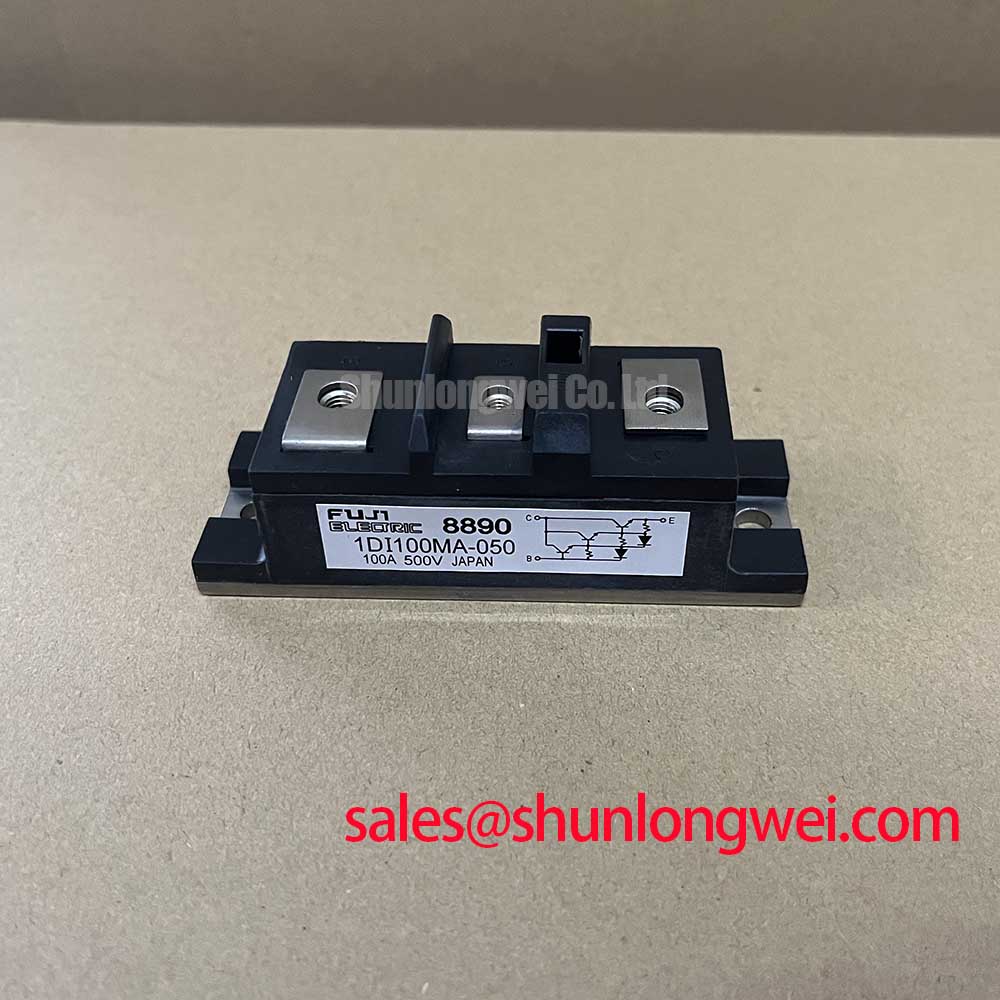
Where the rectifier stage requires a higher current device for a separately documented subsystem, the 2DI200A-050 can be reviewed as a related Fuji Electric diode module. Its use remains subject to terminal layout, circuit function, thermal interface, protection coordination, and full system validation rather than a nameplate comparison alone.