

Content last revised on October 21, 2026
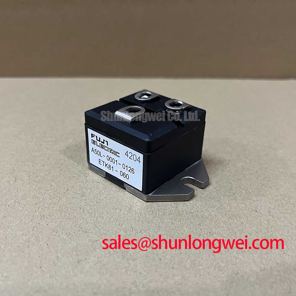
ETK81-060 Inspection and Verification
- Isolate the power assembly, discharge stored energy, and map the ETK81-060 terminal markings to the equipment schematic before connecting test leads.
- Record cold diode-mode readings in both polarities with external parallel paths disconnected, then compare under the same conditions with a known-good reference.
- Inspect the mounting surface, terminal seating, and busbar alignment for conditions that could introduce mechanical stress or uneven contact.
- Check the equipment’s insulation-test procedure separately from the diode reverse-voltage rating before applying any withstand test.
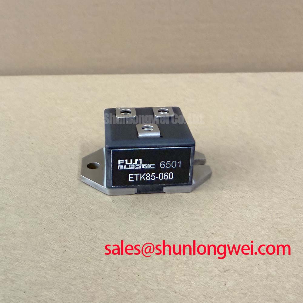
The ETK81-060 is a Fuji Electric diode module with a 600 V repetitive peak reverse-voltage rating and an 80 A average forward-current rating. Incoming inspection should distinguish low-current bench measurements from rated operating characteristics: a multimeter reading does not reproduce the conditions associated with the specified maximum forward voltage.
| Parameter | Official Specification |
|---|---|
| Repetitive peak reverse voltage, VRRM | 600 V |
| Average forward current, IF(AV) | 80 A |
| Reverse recovery time, trr | 0.35 µs maximum |
| Forward voltage, VF | 2.2 V maximum |
| Package | M81 |
| Terminal drawing, mounting torque, test conditions, surge withstand, thermal impedance, and insulation rating | Consult the manufacturer’s datasheet for the applicable limits and conditions. |
Bench Tip: Discharge the isolated assembly before diode-mode testing, and use identical lead polarity and module temperature when comparing cold readings.
Assembly Integrity & Layout Architecture: Implementing Interphase Transformer Current Balancing for ETK81-060
Trace each rectifier branch through its transformer winding, diode connections, and DC bus before evaluating interphase transformer current sharing. As a Design Consideration, a six-pulse bridge and a twelve-pulse arrangement require different transformer and interconnection provisions; the latter commonly combines phase-displaced bridge groups. An interphase transformer belongs to the system architecture, not to the ETK81-060 package specification.
For a potential high-current green hydrogen electrolyzer DC power rectifier, engineers should evaluate the module within the complete branch arrangement rather than infer kiloampere capability from its individual current rating. Current balance depends on winding characteristics, connection resistance, semiconductor conduction behavior, and cooling conditions. Compare branch currents under controlled loading, including changes during warm-up, before accepting a parallel arrangement.
Engineering Recommendation: Fit busbars without forcing the terminals into alignment, and follow the specified tightening sequence and torque for the actual module and connection hardware. Check mating-surface condition and cooling contact before energization. The M81 designation alone does not establish mounting dimensions, screw size, or permissible terminal loading.
For replacement assessment, the 2DI150MA-050 can be included in a documented comparison, but it should not be treated as interchangeable without checking circuit configuration, electrical limits, terminal mapping, and mechanical fit. The Fuji Electric Power Semiconductors Portal provides manufacturer context for identifying the relevant product documentation.
ETK81-060 Operational Boundaries: Evaluating Semiconductor Protection Fuse Selection in Limits
Compare the candidate fuse’s total clearing I²t with the semiconductor’s permitted surge withstand under matching fault conditions. This is a Design Consideration: fuse coordination requires the prospective fault current, circuit voltage, initial junction temperature, and applicable withstand duration, rather than a comparison of continuous-current labels alone.
The ETK81-060’s 80 A average forward-current rating is not a short-circuit withstand specification. A useful coordination record places the fuse’s pre-arcing and total clearing characteristics beside the diode’s surge-current and I²t limits, with their conditions retained. Include fuse interrupting capacity and the installation’s fault-current estimate in that record. Clearing I²t describes accumulated current-squared time, not an independently transferable energy rating.
Engineering Recommendation: Assess the fuse, enclosure, conductors, and upstream protection together; fuse selection alone cannot guarantee damage-free interruption of a dead short. Check terminal connections for looseness or localized heating because connection faults can develop outside the assumptions used for semiconductor protection.
Where the equipment also contains a 2DI100D-100, retain separate component limits and protection requirements for its position in the circuit. Its presence elsewhere in the power assembly does not establish a shared fuse rating or a common surge-withstand envelope.
ETK81-060 Thermal-Electrical Optimization: Minimizing Commutation Turn-Off Voltage—Practical Tuning
Capture reverse voltage and branch current across the commutation interval using appropriately rated probes and a measurement arrangement that minimizes pickup. The specified 0.35 µs maximum reverse recovery time does not independently establish peak reverse recovery current, recovery softness, or switching loss. Those characteristics require their own test conditions and waveform assessment.
Design Consideration: Reduce unnecessary commutation-loop area to limit inductive overshoot, then verify the resulting peak voltage against the module’s repetitive reverse-voltage boundary across the intended operating conditions. Distinguish genuine ringing from probe-loop artifacts before changing suppression components. Any damping or snubber values should follow the measured circuit behavior and system validation.
The 2.2 V maximum forward voltage is not a constant loss value across every load and temperature. Thermal assessment should use the applicable conduction characteristics, cooling interface, and transient thermal data, especially during overload recovery. Manufacturer support channels through Fuji Electric Europe Semiconductor & Power Electronics can help identify appropriate technical resources.
Gate-bias adjustments concern associated controlled switches, not a gate terminal on this diode module. The technical article Evolution of Negative Off-Bias Gate Drive Circuits provides context when investigating neighboring switch behavior. Evaluate that circuitry separately while checking whether its switching transitions alter the ETK81-060’s measured commutation stress.