Content last revised on September 16, 2026
ETK85-060 Circuit Protection & Reliability: Coordinating Primary Spark Gaps and MOVs
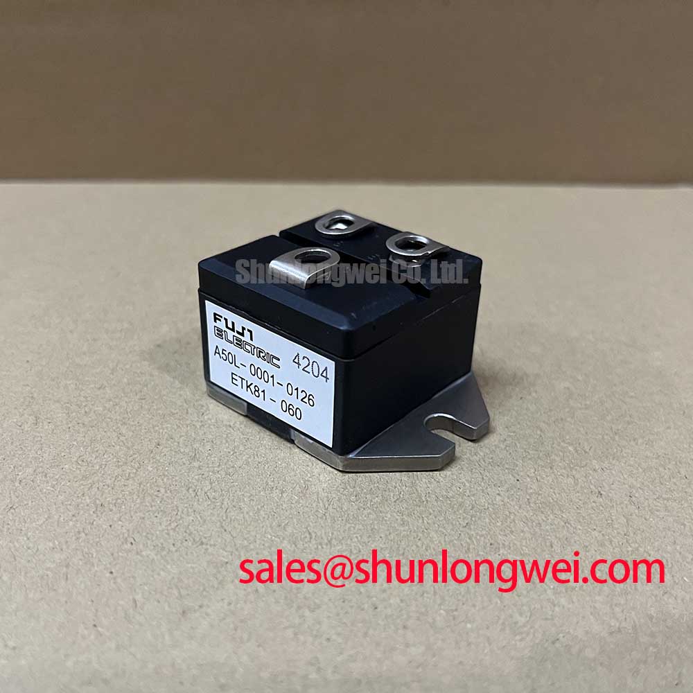
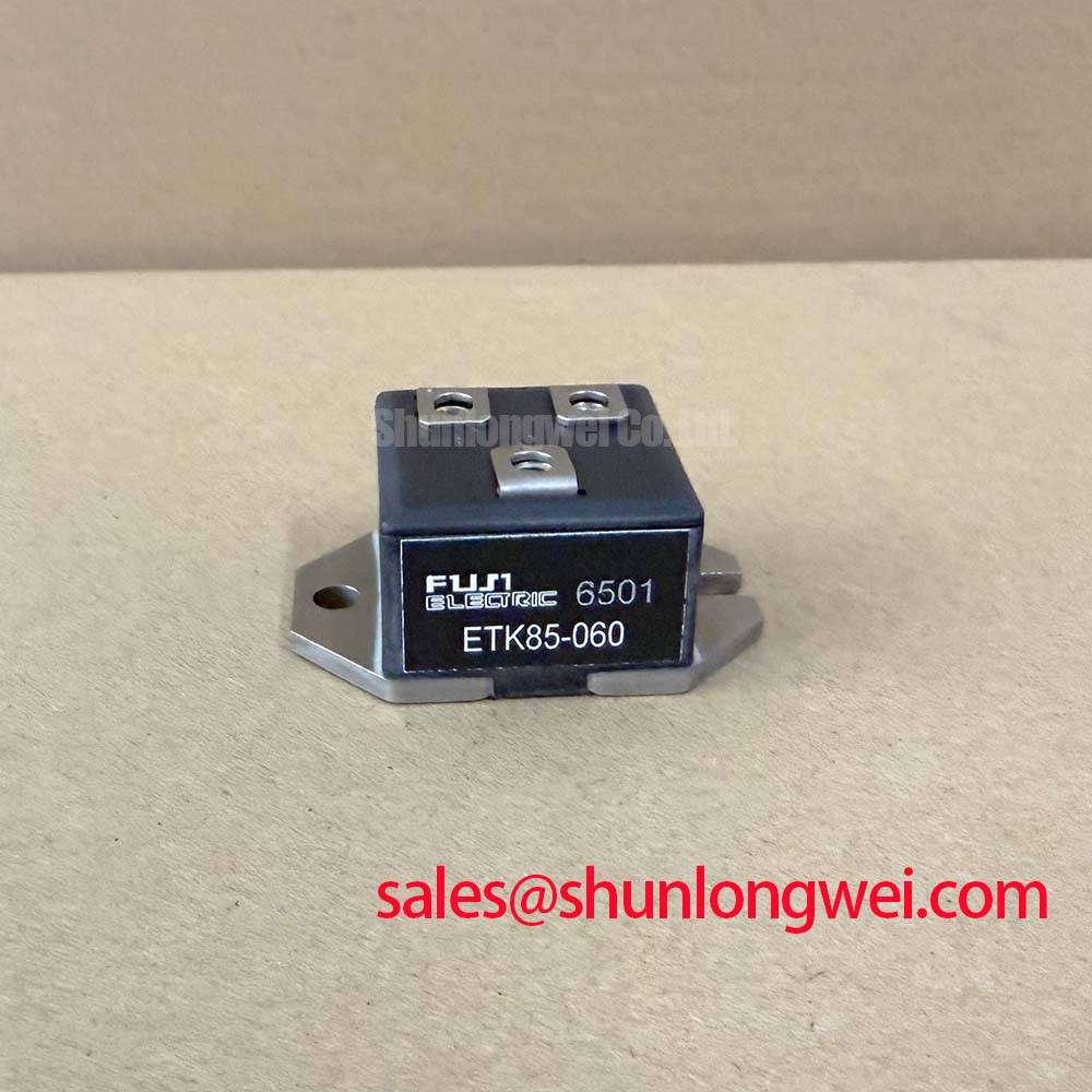
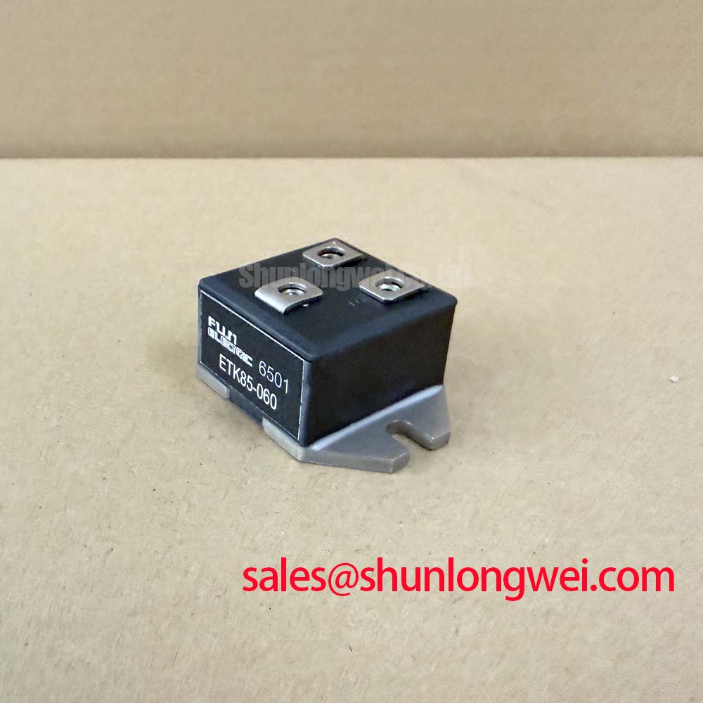
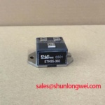
ETK85-060 is a Fuji Electric diode module with an official 600 V repetitive peak reverse-voltage rating, 80 A average forward-current rating, 100 ns maximum reverse-recovery time, 1.5 V typical forward-voltage drop, and 2500 V AC isolation voltage. These values define the electrical boundary of the module itself. They do not establish the voltage, surge, thermal, fuse, or coordination ratings of the completed motor soft starter.
| Official Specification | Value | Engineering Relevance |
|---|---|---|
| Repetitive peak reverse voltage, VRRM | 600 V | Defines the repetitive reverse-voltage limit for the diode junction. |
| Average forward current, IF(AV) | 80 A | Establishes the continuous-current reference under stated manufacturer conditions. |
| Reverse recovery time, trr | 100 ns maximum | Relevant where commutation transients and switching loss require assessment. |
| Forward voltage, VFM | 1.5 V typical | Indicates typical forward conduction loss at the specified test condition. |
| Isolation voltage, Visol | 2500 V AC | Supports insulated mounting arrangements subject to complete system insulation design. |
Start protection review by identifying whether the ETK85-060 is installed as an input rectifier, a freewheel path, or another diode position within the power assembly. The module’s official 600 V VRRM rating is the primary device boundary for repetitive reverse stress. A measured bus voltage alone is insufficient for judging margin because incoming line disturbances, commutation behavior, cable inductance, and the switching state of associated power devices can change the actual voltage at the diode terminals.
In a high-voltage three-phase motor solid-state soft starter, primary spark gaps, MOVs, RC networks, semiconductor fuses, and contactor arrangements are system-level elements. Their selection is a Design Consideration, not an ETK85-060 factory specification. A surge-protection review should confirm the protective path, installation location, grounding arrangement, and the voltage waveform that remains at the module after the protection network responds. Engineers should validate these conditions on the assembled equipment, including the intended line configuration and operating load.
Fuse coordination requires the actual fuse documentation, fault-clearing characteristics, prospective fault current, conductor arrangement, and the semiconductor device data applicable to the installed topology. Do not infer an I2t coordination value from the 80 A IF(AV) rating. Average current describes a defined operating condition; it does not identify fault survival capability or replace a complete protective-device study.
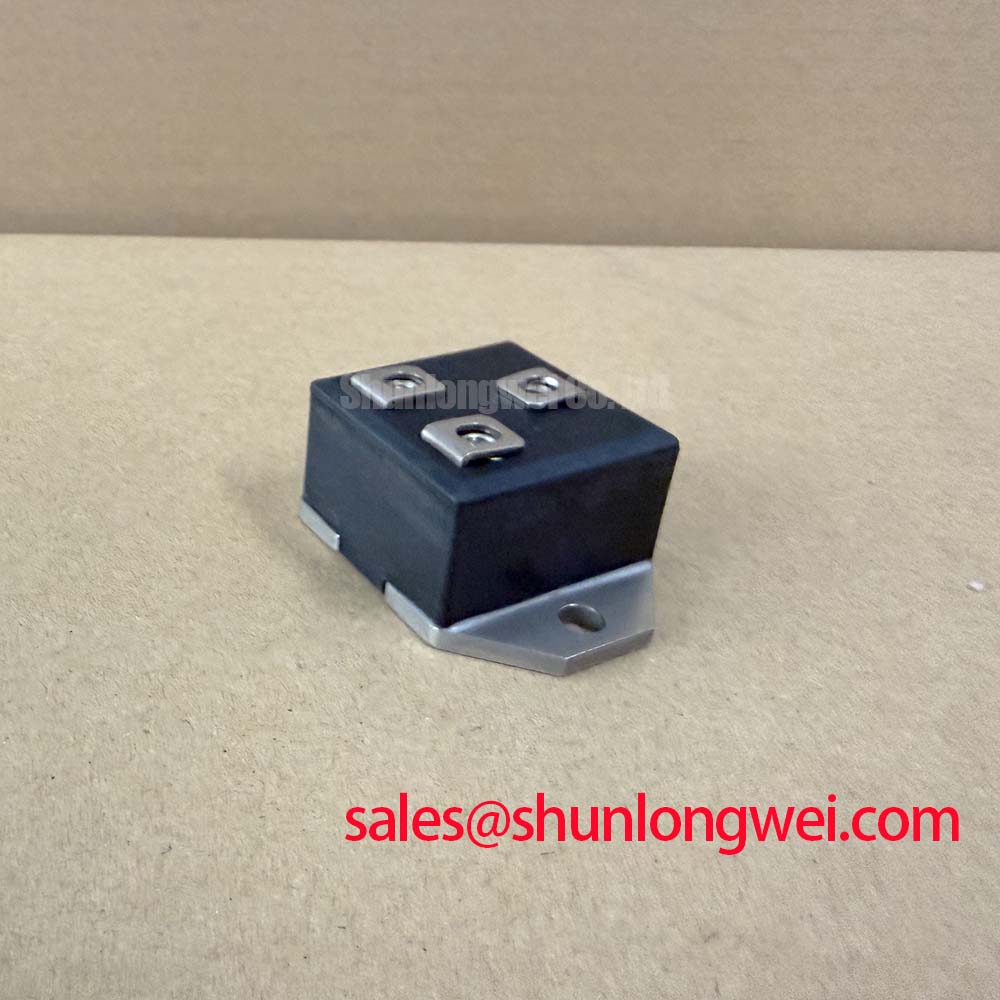
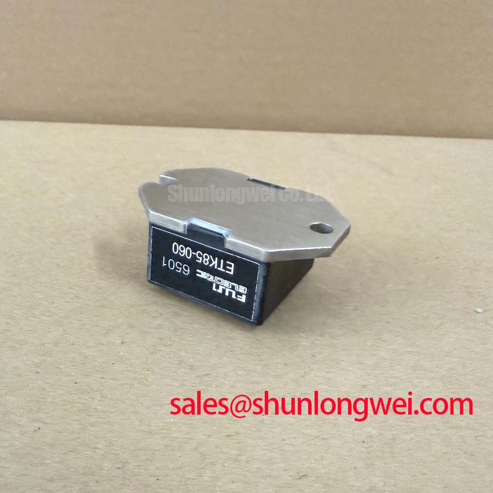
The 2500 V AC isolation voltage is an official module parameter and is relevant to the insulation barrier between the electrical circuit and the mounting interface. It should not be treated as a complete enclosure, creepage, clearance, or installation certification claim. During service, inspect for contamination, cracked insulation, damaged terminal hardware, and uneven mechanical loading. The required mounting hardware, tightening sequence, torque, thermal-interface material, and conductive path must be verified from the original equipment documentation and the applicable Fuji Electric mechanical documentation.
Field Alert: De-energize, lock out, and verify absence of stored energy before loosening terminal hardware or handling a module connected to a DC-link assembly.
Where a rectifier stage must be evaluated alongside related devices, the 2DI75D-050A can be reviewed as a separate diode-module reference, but terminal layout, ratings, insulation arrangement, and the original circuit function must be verified before any service decision.
Preventing Spurious Faults: High-di/dt Gate Firing: Pulse-Train Timing Guidelines for ETK85-060
The ETK85-060 is a diode module, so it has no gate terminal, gate-firing pulse specification, holding-current parameter, or gate-drive timing requirement. Gate pulse rise time, back-porch current, pulse-train firing, and localized gate heating belong to controlled devices such as thyristors or IGBTs in the surrounding soft-starter circuit. Treating the ETK85-060 as a gated device would lead to an invalid diagnostic procedure.
When a soft starter shows unstable firing, uneven phase current, or unwanted commutation behavior, separate the investigation into two paths. Examine the control board, isolation interfaces, firing transformers or gate-driver channels, and controlled power devices according to their own documentation. Independently inspect the diode module’s installed polarity, conductor security, thermal contact, and measured voltage stress. This avoids using a gate-drive diagnosis to draw conclusions about an ungated rectifier module.
Reverse recovery is the relevant ETK85-060 switching characteristic supplied here. The official 100 ns maximum trr indicates the maximum specified reverse-recovery time. Its practical impact depends on the commutation current, current slope, circuit inductance, temperature, and the behavior of the mating devices. A scope trace that exhibits ringing or an unexpected recovery transient may indicate several possible contributors, including bus geometry, snubber condition, probe setup, control timing, or a connection issue. Compare the waveform with a known-good channel or validated system reference before assigning a cause.
Design Consideration: minimize the physical loop area of each high-current commutation path to help suppress inductive overshoot during current transfer, then verify peak device stress at the assembled system terminals. This is especially important where diode commutation occurs close to controlled semiconductor branches. For wider context on power-semiconductor operating principles, see The Ultimate IGBT Knowledge Base.
The physical mechanisms of semiconductor channel control differ across device families. For example, high-electron-mobility transistor operation is associated with a two-dimensional electron gas, as outlined in this HEMT technical reference; that behavior should not be used to infer ETK85-060 diode characteristics. For this module, rely on the published diode ratings and measured conditions in its installed circuit.
Benchtop Waveform Tuning: Mitigating Stress via AC-to-DC Transfer Characteristics across V on ETK85-060
AC-to-DC transfer characteristics in a phase-controlled soft starter are determined primarily by the topology and firing angle of the controlled semiconductor devices. A firing-angle range from zero to 150 degrees is therefore a controller-level test condition, not an adjustable ETK85-060 parameter. The diode module must be evaluated according to its actual role in the associated current path rather than as the element that sets phase-angle control.
For bench verification, use an isolated measurement arrangement appropriate to the equipment voltage and capture line-to-line voltage, load current, DC-path voltage where applicable, and relevant controller timing. The aim is to establish whether diode conduction and reverse blocking occur where the circuit topology predicts. Test results should be interpreted against the original schematic, phase sequence, load condition, and the controller’s commanded firing state.
The official 1.5 V typical VFM supports a first-order view of diode conduction loss, but it is not a fixed operating voltage across every current and temperature condition. It should not be multiplied into a thermal conclusion without the relevant current waveform, duty cycle, thermal path, and manufacturer test conditions. A higher-than-expected temperature rise may arise from current imbalance, weak heatsink contact, airflow changes, contaminated interfaces, parallel-path behavior, or abnormal commutation rather than one single condition.
Reactive-power demand and power factor are properties of the complete phase-controlled system. When commissioning or repairing a motor soft starter, engineers should verify supply quality and load current while varying controller command states under controlled conditions. The 80 A IF(AV) rating should be respected as an official module value, while the permissible application current must be established from the original system thermal design and waveform analysis.
For cross-model assessment, 2DI200A-050 is a separate diode-module reference. It should not be considered electrically or mechanically interchangeable solely because both products are used in power rectification. Confirm circuit position, reverse-voltage demand, current waveform, terminal arrangement, isolation requirements, mounting geometry, and the original equipment design before evaluating any replacement path.
Benchtop Waveform Tuning: Mitigating Stress via Thermal Avalanche Margins during High Peak on ETK85-060
The provided official specification set does not state an ITSM surge-current rating, avalanche rating, junction-temperature limit, thermal resistance, or fuse I2t value for ETK85-060. Those values must not be assumed from the 80 A average-current rating or from visual similarity to another diode module. Obtain the applicable manufacturer documentation before defining surge tolerance, overload capability, or a protection coordination limit.
For a sinusoidal half-cycle surge investigation, do not apply a deliberate overload test until the original design documentation, protective-device behavior, test equipment ratings, and safety controls have been reviewed. A high-peak event can place simultaneous electrical and thermal stress on the module, buswork, fuse system, and mating controlled devices. Post-event reverse-voltage reapplication should be assessed from measured system behavior and validated against documented device limits.
Thermal integration remains essential even where the apparent issue is electrical. Confirm that the module mounting face and heatsink are clean, flat within the equipment’s specification, and free of damage that could compromise contact. Apply the thermal interface material according to the original assembly requirement, use the specified hardware, and tighten connections in the prescribed sequence. These are Engineering Recommendations for repeatable assembly, not unverified ETK85-060 factory mechanical ratings.
During controlled commissioning, compare phase currents and device-area temperatures across equivalent operating states. An unexpected difference may indicate a system-level condition requiring further isolation, such as unequal current paths, a control timing discrepancy, degraded cooling, or measurement error. Preserve the waveform captures and maintenance observations with the equipment record so later repairs can be compared against an established baseline.