
Content last revised on August 28, 2026
Evaluating Post-Surge Reverse Voltage Blocking Recovery at Elevated Junction Temperatures
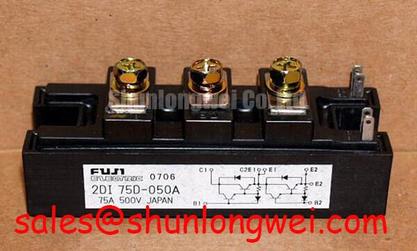
In high-current green hydrogen electrolyzer DC power rectifiers, continuous electrochemical loads push power stages near their thermal limits. The 2DI75D-050A dual Darlington power module is rated for a continuous collector current IC of 75 A, a pulsed collector current ICP of 150 A, and a maximum collector-base voltage VCBO of 600 V. Operating under sustained DC bus demands requires precise validation of the sustained collector-emitter voltage VCEO(SUS) of 500 V, particularly following sub-cycle transient overloads.
When line disturbances or rapid electrolyzer load steps generate short-duration current surges, the internal silicon junction temperature can rise toward its maximum threshold of Tj = +150°C. As junction temperatures elevate, reverse leakage currents increase exponentially, reducing the dynamic voltage-blocking margin. Plant maintenance personnel must ensure that semiconductor protection fuses are selected with an I2t let-through rating well below the module's thermal withstand boundary. For comprehensive methodologies on thermal runaway prevention and junction degradation diagnostics, plant technicians can reference the Field Engineer’s Handbook.
Dynamic Voltage Sharing and RC Damping in Series-Connected Rectifier Diodes
Multi-pulse industrial rectifier arrangements frequently utilize bridge topologies where power semiconductors experience steep dv/dt commutations. The 2DI75D-050A requires a continuous base current IB of 4.5 A to maintain deep saturation and keep on-state conduction losses within allowable limits. When switching inductive busbars, unbalanced reverse recovery characteristics across parallel or series branches can trigger localized current crowding and transient overvoltages.
Proper snubber design using dedicated RC damping circuits across the collector-emitter terminals suppresses high-frequency ringing and prevents transient excursions from exceeding the 500 V VCEO(SUS) threshold. In mixed-topology installations requiring alternative current ratings or companion rectification stages, industrial systems frequently pair this unit with the complementary 2DI100MA-050. Standardized switching behavior and driver design criteria can also be verified through technical documentation provided by Fuji Electric Power Semiconductor & IPM Modules.
| Parameter | Symbol | Rated Value | Operating Significance |
|---|---|---|---|
| Collector-Emitter Sustained Voltage | VCEO(SUS) | 500 V | Max sustained operating DC margin across electrolyzer rails |
| Collector-Base Voltage | VCBO | 600 V | Peak blocking rating with open base circuit |
| Continuous Collector Current | IC | 75 A | Maximum DC delivery per stage under rated case temperatures |
| Peak Collector Current | ICP | 150 A | Transient pulse headroom during cell stack startup |
| Continuous Base Drive Current | IB | 4.5 A | Required saturation current to prevent excessive VCE(sat) dissipation |
| Maximum Power Dissipation | PC | 250 W | Total thermal dissipation allowance per module at Tc = 25°C |
| Dielectric Isolation Voltage | VISO | 2500 V AC | 1-minute isolation safety between terminals and copper baseplate |
AC Input Transient Overvoltage Clamping ahead of Silicon Rectifier Junctions
Electrolyzer rectifiers connected to medium-voltage step-down transformers are exposed to line-side switching transients, lightning surges governed by IEEE 61000-4-5, and power factor correction cap-bank switching. Safeguarding the 2DI75D-050A against destructive overvoltage punctures requires coordinated Metal Oxide Varistors (MOVs) and fast-acting suppression networks placed directly at the primary AC input stages.
Because the module features an isolation rating of VISO = 2500 V AC (1 min) between active terminals and the copper baseplate, adequate electrical clearance and creepage must be maintained on busbar routing. For legacy rectifiers undergoing capacity reconfiguration or requiring higher power handling across identical mounting footprints, engineers often inspect the compatible 2DI150Z-100 alongside modern integration topologies documented in Fuji Electric PIM (Power Integrated Module) 7-Pack architectures.
Thermal Interface Material Spreading across Heavy Copper Baseplates
Continuous operation at maximum power dissipation (PC = 250 W) generates localized heat flux that must conduct efficiently across the heavy copper baseplate into the forced-air or liquid-cooled heatsink. Non-uniform thermal interface material (TIM) application creates localized hot spots, leading to premature die breakdown well before the external case temperature reaches nominal trip thresholds.
⚠️ Field Alert: During preventive maintenance intervals, inspect thermal paste for degradation, drying, or pump-out effect caused by thermal cycling. Apply non-silicone thermal grease in a uniform layer between 50 µm and 80 µm. Tighten the module mounting screws using a calibrated torque wrench in a diagonal two-step sequence (initial snug at 1.0 N·m, final torque to 1.5–2.0 N·m). Over-torquing deforms the internal ceramic substrate, whereas under-torquing drastically increases case-to-heatsink thermal resistance.
Preventive maintenance teams must also implement quarterly heatsink air-channel cleaning in harsh chemical or hydrogen plant atmospheres to prevent dust encapsulation, maintaining operational reliability within the safe operating envelope of -40°C to +150°C.