


Content last revised on October 10, 2026
2DI75D-100 Circuit Protection & Reliability: Calibrating AC-to-DC Transfer Characteristics
Isolate the AC input, verify that stored energy has discharged, and disconnect parallel circuit paths before checking the 2DI75D-100 terminals with a multimeter. Compare forward and reverse readings with the equipment schematic and a known-good assembly; an in-circuit reading can include transformer windings, snubbers, or other semiconductor paths. Persistent low resistance in both directions warrants further isolation rather than an immediate diagnosis from one measurement.
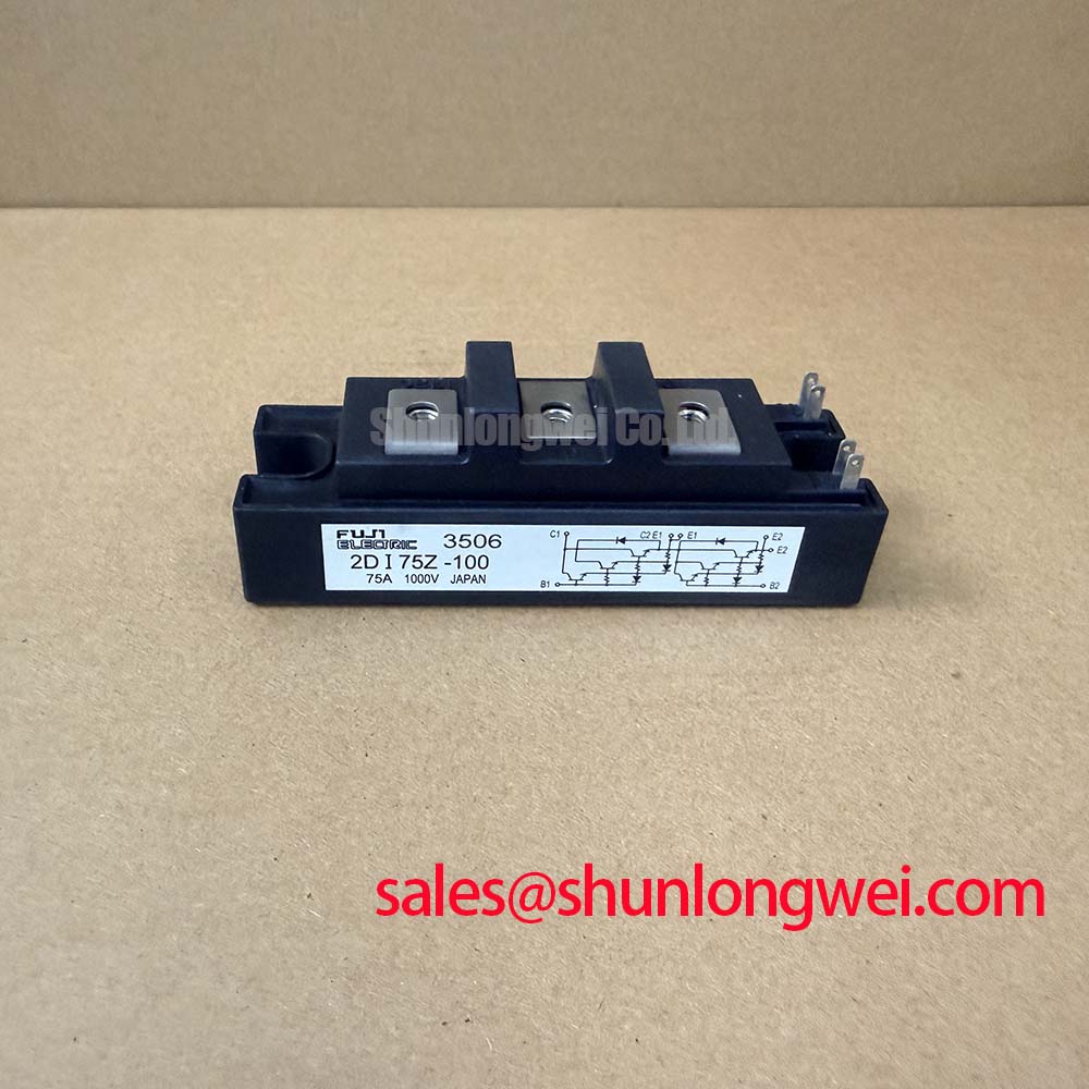
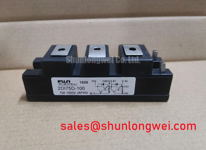
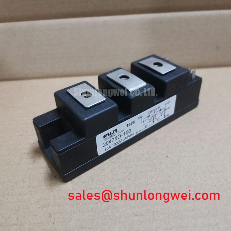
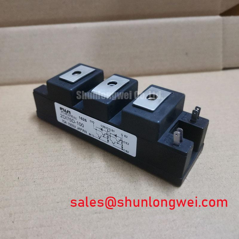
The Fuji Electric 2DI75D-100 has specified ratings of 1000 V and 75 A, with the package identified as a Power Diode Bridge Module. These product ratings are the starting point for electrical screening, not a substitute for checking terminal arrangement, operating conditions, and mechanical fit.
Separate diode conduction from firing-angle control when tracing the AC-to-DC power path. A diode does not receive a firing command: any controlled conduction angle belongs to thyristors or other controlled switches elsewhere in the assembly. Establish the actual circuit connections before assigning an AC-to-DC transfer characteristic to this module.
As a Design Consideration, an upstream phase-controlled stage swept from 0° to 150° changes the conduction window and current waveform presented to downstream components. The resulting average DC voltage depends on rectifier topology, load inductance, and whether current remains continuous. Delayed firing can increase displacement-related reactive demand, while discontinuous current adds harmonic distortion; measure input voltage and current together rather than interpreting power factor from firing angle alone.
For compatibility assessment in a high-voltage three-phase motor solid-state soft starter, engineers should establish whether the module occupies a rectifying or auxiliary power path rather than the controlled motor-switching position. Match terminal functions to the equipment drawing before reconnecting busbars. A similar enclosure does not establish an equivalent internal circuit.
For short-circuit protection, build the fuse coordination record around prospective fault current, semiconductor surge withstand, and the fuse’s total clearing I²t at the applicable voltage. As an Engineering Recommendation, include clearing-time behavior and interrupting capacity alongside the energy comparison. A semiconductor fuse’s current rating alone cannot establish protection against a hard short circuit, and no module-specific fuse selection follows from the 75 A rating alone.
Benchtop Waveform Tuning: Mitigating Stress via Coordination of Primary Spark Gaps, MOVs, on 2DI75D-100
Capture transient voltage at the module terminals with probes suitable for the circuit’s voltage and common-mode conditions. Use IEC 61000-4-5, rather than “IEEE 61000-4-5,” when specifying surge-immunity testing. It provides a system test framework; it does not establish independent surge certification for this diode module.
As a Design Consideration, coordinated spark-gap and MOV protection should account for supply characteristics, surge energy, protective-device tolerances, and wiring impedance. Assess the residual voltage reaching the semiconductor, not simply the MOV’s nominal designation. Where thyristors exist elsewhere in the circuit, their protection requirements remain separate from those of the diode module.
An RC snubber can damp circuit ringing, but its component values belong to the measured circuit. Engineers should evaluate ringing frequency, repetitive dissipation, and current introduced by the snubber before selecting values. Keep the protection loop compact to reduce additional inductive overshoot, then verify the waveform at the protected terminals.
When assessing the related 2DI100D-100, use a comparison record rather than treating the part number as proof of direct interchangeability.
| Selection checkpoint | 2DI75D-100 | 2DI100D-100 assessment |
|---|---|---|
| Specified voltage | 1000 V | Consult datasheet |
| Specified current | 75 A | Consult datasheet |
| Package identification | Power Diode Bridge Module | Verify outline and terminal circuit |
| Replacement acceptance | Reference component | Compare electrical, thermal, and mounting requirements |
The 2DI150MA-050 is another component to assess when reviewing a separate rectifier or auxiliary stage; its suitability must follow that stage’s electrical requirements, not an assumed complementary pairing.
2DI75D-100 Circuit Protection & Reliability: Calibrating High-Frequency Switching Loss Dissipation
Measure commutation current and reverse voltage together when investigating heating or ringing around the 2DI75D-100. As a Design Consideration, reverse-recovery peak current and recovery duration depend on operating conditions, including forward current, temperature, and commutation rate. Do not classify this device as soft-recovery or suitable for high-frequency switching solely from its voltage and current ratings.
Separate conduction heating from commutation loss by comparing waveform behavior with case-temperature trends under controlled loading. For pulse operation, an Engineering Recommendation is to evaluate junction-temperature rise using the applicable transient thermal impedance curve and actual pulse sequence. Mounting contact and heatsink performance must also enter that assessment.
Field Alert: Follow the module’s specified fastening procedure and interface-material instructions rather than applying a generic torque value to its terminals or mounting screws.
Fuji Electric’s power semiconductor resources provide manufacturer context for component evaluation. The system-level discussion in The Race for Efficiency offers broader thermal-integration context, not a lifetime qualification for this model. Close the repair assessment with recorded terminal waveforms, load conditions, mounting checks, and thermal behavior against the equipment’s acceptance limits.