

Content last revised on September 20, 2026
DD89N18 Thermal-Electrical Optimization: Mechanical Mounting Torque Sequence and Practical Tuning
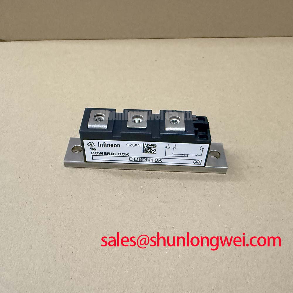
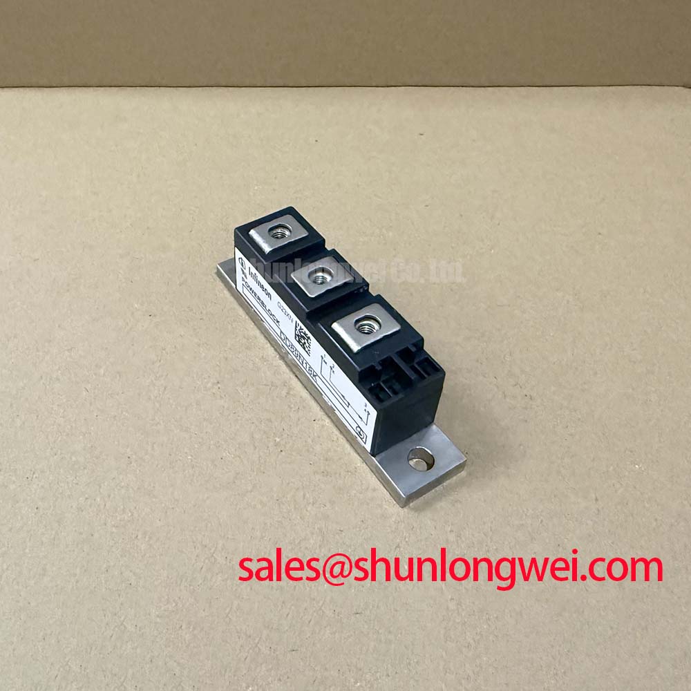
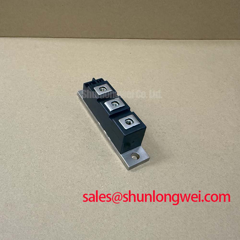
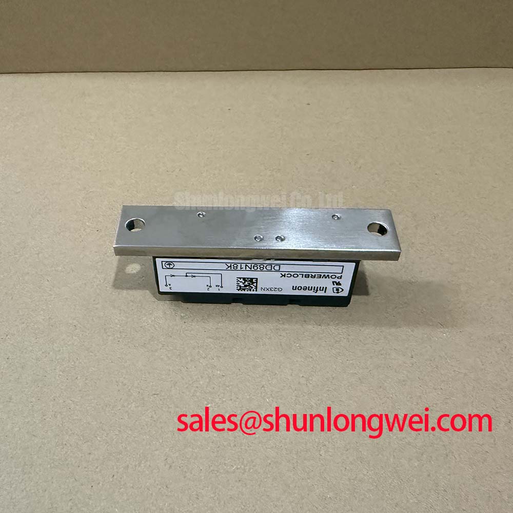
Begin the bench check by comparing the nameplate and purchase record with the required electrical boundary, then inspect the power terminals, case, and baseplate for contamination, cracking, or mounting distortion. The Infineon DD89N18 is identified for this page as a 1800.0 V, 89.0 A diode module in a PowerBlock Module package. These are the available official product parameters; switching, surge, thermal-resistance, and mechanical-torque values must be confirmed against the applicable manufacturer documentation before design release.
| Parameter | DD89N18 Specification |
|---|---|
| Manufacturer | Infineon |
| Product category | Diode Module |
| Rated voltage | 1800.0 V |
| Rated current | 89.0 A |
| Package | PowerBlock Module |
For a high-current green hydrogen electrolyzer DC power rectifier, the first integration task is to establish a flat, clean thermal interface between the module base and the heatsink. The DD89N18 rating of 89.0 A does not by itself define the permitted continuous operating current in a particular rectifier. Actual current capability depends on cooling architecture, ambient conditions, waveform, electrical layout, and the manufacturer’s complete thermal data.
Use the equipment service procedure to clean the heatsink contact area and inspect for burrs, uneven contact, or aged thermal-interface material. Fasteners should be tightened in a controlled sequence that distributes pressure across the baseplate. The correct mounting torque is a manufacturer and hardware specific value, so the system engineer should verify the applicable DD89N18 mechanical specification rather than applying an assumed torque. Excessive or uneven pressure may distort the package or produce inconsistent thermal contact.
Terminal connections require the same discipline. Confirm the conductor size, lug geometry, insulation clearance, and terminal torque from the equipment drawing and applicable module documentation. After commissioning, compare terminal temperature and heatsink temperature under a known load. A rising temperature trend can justify checking airflow, dust accumulation, interface-material condition, busbar alignment, and current sharing across parallel paths.
⚠️ Maintenance Note: Isolate power before retorquing terminals, and periodically inspect heatsink cleanliness, thermal-interface aging, and airflow direction.
The DD89N18 may be evaluated in the rectifier stage of a high-current electrolyzer power supply, subject to system validation. In a complete power chain, engineers may also review a suitable upstream rectifier or complementary stage such as TD210N12; that device is a separate product and is not a specification of the DD89N18.
Preventing Spurious Faults: Surge and Thermal Margins During High-Peak Operation for DD89N18
High peak current events should be assessed from measured operating waveforms rather than from the nominal current rating alone. The listed 1800.0 V voltage rating and 89.0 A current rating identify the product category and principal electrical boundary, but they do not provide the complete allowable surge profile for a particular installation.
During rectifier commissioning, record the line waveform, DC output current, commutation behavior, and heatsink temperature under the highest intended operating condition. If the circuit experiences a short-duration peak or a fault-clearing event, the engineer should verify the applicable sinusoidal half-cycle surge-current rating, junction-temperature limit, and I²t coordination data in the relevant manufacturer documentation. These values should not be inferred from the 89.0 A rating.
Fuse coordination is a system-level protection task. Selective protection requires comparison of the fuse clearing characteristic with the diode module’s permitted non-repetitive current and energy limits. The fuse I²t value, prospective fault current, wiring impedance, and DC-link energy all influence the result. Verify the complete protection network before applying the module to a high-energy rectifier.
After a fault or abnormal overcurrent event, do not rely only on a visual inspection. Check insulation condition, terminal tightness, phase balance, and the known-good signal and power paths with appropriately rated test equipment. Reapplication of reverse voltage should follow the equipment service procedure after the source of the abnormal event has been investigated.
Transient Dynamics & Electrical Design: High-Frequency Switching Loss Dissipation on DD89N18
A diode module in a controlled rectifier can experience commutation stress when current transfers between semiconductor paths. Reverse-recovery peak current, recovery time, softness, stray inductance, and switching frequency all affect voltage overshoot, switching loss, and conducted or radiated disturbance. No reverse-recovery figures were provided in the defined product parameters for this page, so the system integrator should obtain the applicable DD89N18 data before calculating loss or selecting a switching strategy.
Keep the high-current commutation loop compact and route forward and return conductors together where the equipment topology permits. This is a Design Consideration, not a guaranteed electrical limit for the module. During testing, use a measurement arrangement suitable for the voltage and current involved, then compare observed peaks with the verified module voltage boundary and the rectifier’s insulation coordination requirements.
Gate-drive functions such as desaturation protection, soft shutdown, negative gate bias, bootstrap capacitor charging, and gate-loop common-mode noise control apply to controlled semiconductor switches, not automatically to a diode module. The DD89N18 should therefore be assessed according to its diode-module terminals and rectifier role. If the wider converter contains IGBTs or other controlled devices, those protection circuits must be validated separately rather than attributed to this diode module.
For a broader topology discussion, engineers can consult The 1200 V CoolSiC™ MOSFET Advantage in Three. That technical article concerns a different semiconductor technology and should not be treated as a DD89N18 datasheet.
Benchtop Waveform Tuning: Mitigating Stress via Phase-Controlled Rectification and Firing Angle
When the DD89N18 is evaluated in a phase-controlled rectifier, firing-angle adjustment changes the average DC output, input displacement behavior, and reactive-power demand. The exact transfer characteristic depends on bridge topology, supply configuration, source impedance, overlap, load type, control timing, and commutation conditions. Designers should derive the operating range from the actual circuit and verify it with isolated voltage and current measurements.
A bench test should begin with the lowest practical energy state and a defined load. Record firing commands, phase voltage, diode current, DC output voltage, and any commutation overlap. Increase the operating point only after confirming that the measured waveform remains within the verified 1800.0 V voltage boundary and the applicable thermal and current limits. The stated 89.0 A value should not be treated as a universal rating for every waveform or cooling condition.
Power factor correction, harmonic-current limits, and upstream transformer loading belong to the complete rectifier system. The equipment designer should verify these conditions against the electrolyzer power-conversion specification and applicable installation requirements. Infineon’s information on Automotive Qualified Power Modules and Intelligent Power Modules describes other product families and should be used only for comparative architecture research.
For service replacement, confirm the original module’s voltage class, current requirement, package dimensions, terminal arrangement, cooling interface, and protection coordination before procurement. A related product can be reviewed as a neutral comparison point through DDB6U180N16RRP_B37, but substitution requires system-level electrical, mechanical, thermal, and control verification.