Content last revised on September 28, 2026
Field Diagnostics & Commissioning: Half-Cycle Surge Current in DSEI2X61-06C Topologies
For a failed rectifier position, first document which terminals connect to the source, load and any associated protection device. With the module disconnected as required for a meaningful reading, compare forward and reverse diode measurements with the circuit drawing and a known-good assembly where available. An unexpected reading warrants investigation of parallel circuit paths, meter polarity and terminal identification before attributing the fault to the module.
A half-cycle surge assessment requires the manufacturer’s ITSM rating and its stated initial junction temperature and reverse-voltage reapplication conditions. None of those values is established by the supplied 600 V and 60 A ratings. Likewise, fuse coordination needs the diode’s published I²t limit alongside the fuse manufacturer’s let-through data at the relevant fault current. Do not treat the 60 A rating as a permissible half-cycle surge current. This is a Design Consideration: a protection decision should remain open until both sets of published conditions can be compared.
At commissioning, inspect the terminal hardware for looseness or visible heat damage and verify tightening requirements against the applicable manufacturer drawing and fastener specification. No mounting-torque value is established by the supplied product parameters. If a SKN320-04 appears in a service parts comparison, assess its diode configuration, terminal layout, package, surge data and thermal limits separately; a shared rectification role does not make it a drop-in replacement.
Assembly Integrity & Layout Architecture: Implementing Reverse Recovery Charge for DSEI2X61-06C
In a commutating rectifier path, current can briefly continue in the reverse direction while stored charge is removed. That behavior affects the adjacent switch’s current peak and the voltage ringing seen at nearby conductors. The supplied parameters do not give reverse-recovery charge, peak reverse-recovery current, recovery time or a softness factor for DSEI2X61-06C. Avoid inserting values inferred from another diode into a loss or filter calculation.
For a repair evaluation, compare oscilloscope captures taken at the same operating condition and probe location against a known-good signal path. Review the diode current transition together with the switching-node voltage; a changed waveform may involve the diode, loop layout, snubbing or operating temperature. This is a Design Consideration, not a device-specific diagnosis. Keeping commutation conductors compact can help limit parasitic inductance, but the acceptable peak voltage and switching loss must be verified in the assembled system against its rated boundaries.
A diode has no gate terminal. If an adjacent IGBT uses negative off-bias to manage unwanted turn-on, that is a separate switch-drive decision, not a setting for this module. Evolution of Negative Off-Bias Gate Drive Circuits provides background for reviewing that neighboring drive circuit without conflating its behavior with diode reverse recovery.
Assembly Integrity & Layout Architecture: Implementing Junction-to-Heatsink Heat Dissipation for DSEI2X61-06C
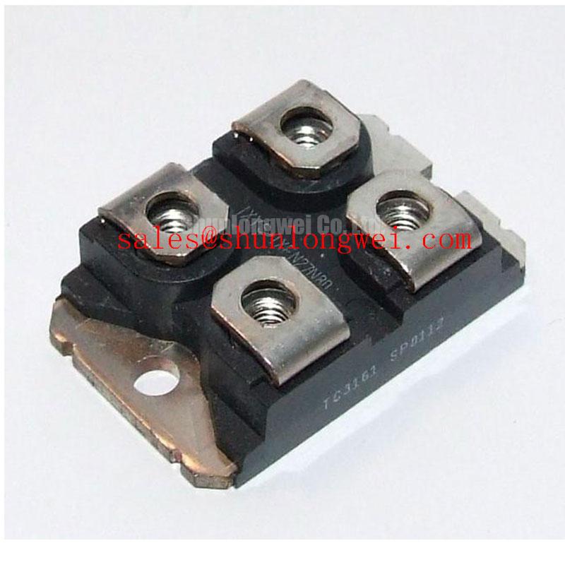
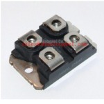
Inspect the mounting face and heatsink contact area before reassembly. Debris, uneven contact or misplaced hardware can compromise the thermal path even when the replacement carries the same SOT-227B / TO-240AA package designation. Apply interface material and fastener load according to the relevant assembly instructions, then check that the seated module is not visibly distorted.
The supplied official parameters do not specify junction-to-case thermal resistance, case-to-heatsink resistance, mounting torque or maximum junction temperature. A temperature-rise assessment therefore needs the applicable manufacturer thermal data, expected conduction losses and measured operating conditions. As a Design Consideration, compare temperatures at repeatable load and ambient conditions after assembly; an unusual rise calls for examination of current sharing, electrical connections and thermal contact rather than an assumption that paste alone is responsible.
Pro Tip: Keep the associated current path physically compact to reduce inductive overshoot during commutation, then verify the assembled circuit’s peak-voltage margin under its actual switching conditions.
Transient Dynamics & Electrical Design: Harmonic Current Injection and Line Filter on DSEI2X61-06C
When evaluating DSEI2X61-06C for an auxiliary rectifier position in a three-phase motor solid-state soft starter, distinguish that position from the phase-control switches. The diode does not accept a firing command and has no firing angle, gate-trigger current or gate-trigger voltage. Claims about output control across firing angles belong to the surrounding controlled topology and cannot be derived from this module’s 600 V and 60 A ratings.
Trace the actual conduction path on the equipment schematic before assessing input-current harmonics or line-filter changes. Measure current and voltage at the relevant terminals through the operating cycle, then compare the results with the equipment’s established acceptance criteria. Power factor and reactive demand depend on the complete circuit and its control strategy; neither is an individual-diode specification. If current measurement uses a fluxgate-based transducer, fluxgate operating principles offer background on the sensing method, not evidence of this diode’s electrical performance.
Before energizing the repaired assembly, confirm terminal orientation against the circuit drawing, inspect the mechanical joint and check that protection and thermal evaluations use data applicable to this exact device position. Record measured waveforms under the equipment’s defined test conditions so later troubleshooting can distinguish a circuit-level change from an unsupported assumption about the diode.