
Content last revised on September 17, 2026
DSEI2X101-06A Operational Boundaries: Evaluating Current and Temperature Limits
Before fitting DSEI2X101-06A, isolate the equipment, discharge the DC link under the site procedure, and confirm that the original rectifier position requires a dual ultrafast diode module rather than a gate controlled semiconductor. This IXYS part has no gate terminal, firing current, holding current, or firing angle specification; it is a dual diode module intended for rectification and freewheel paths where the circuit determines conduction timing.
The official ratings identify a 600 V repetitive peak reverse voltage, 96 A average forward current per diode at TC = 70°C, and 2500 V RMS isolation voltage. Its specified reverse recovery is 35 ns typical and 50 ns maximum, while maximum forward voltage is 1.25 V at IF = 100 A. The 0.15 K/W junction to case thermal resistance supports thermal-path evaluation when the module is mounted to a suitably prepared heatsink.
For maintenance work, the decisive initial check is whether the measured circuit duty remains inside the module’s official electrical boundaries. The 600 V VRRM rating is the blocking-voltage limit for repetitive reverse conditions. In equipment supplied from 240 V or 380 V AC systems, engineers should evaluate the complete rectifier topology, line variation, transformer behaviour, load inductance, switching overshoot, and protective devices rather than treating the nominal mains voltage as the sole selection criterion.
The official 96 A IFAVM per diode rating is stated at TC = 70°C. That case-temperature condition matters during replacement assessment because a contaminated heatsink, restricted fan path, degraded thermal interface material, or uneven mounting surface can produce a case temperature unlike the datasheet condition. A rising enclosure temperature does not establish a diode fault by itself, but it should prompt verification of airflow, heatsink cleanliness, mechanical contact, and operating current against the original system documentation.
The published forward-voltage limit of 1.25 V at IF = 100 A provides a useful conduction-loss reference. During a controlled bench check, compare each diode path with the serviceable circuit path or with the manufacturer-defined test method. A basic meter check can reveal an obvious open or short condition, but it cannot confirm high-current forward loss, reverse recovery performance, isolation integrity under rated stress, or thermal behaviour under load.
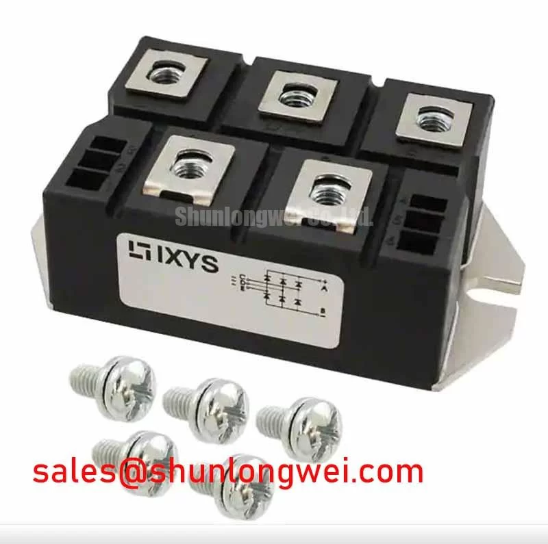
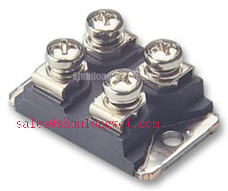
DSEI2X101-06A is supplied in an isolated SOT-227B baseplate format with an official 2500 V RMS VISOL rating. The rating supports the module’s isolation specification, but the installed assembly also depends on the heatsink, mounting hardware, contamination level, cable routing, enclosure design, and the system’s verification procedure. Engineers should retain the original creepage and clearance arrangement when replacing the module.
⚠️ Maintenance Note: Inspect contact-temperature rise and confirm that the cooling air path remains clear before returning a high-current rectifier assembly to service.
Mounting torque is not provided in the stated official parameter set for this part. As a Design Consideration, use the torque and fastening sequence defined by the equipment maker or the applicable IXYS mechanical documentation, then inspect for flat seating and uniform thermal compound coverage. Do not infer a torque value from the electrical ratings alone.
Transient Dynamics and Electrical Design: Protecting DSEI2X101-06A During Fast Recovery
The reverse-recovery specification is central to this module’s behaviour in high-frequency or commutating current paths. The official 35 ns typical and 50 ns maximum trr values describe a fast recovery transition, which can reduce stored-charge-related loss compared with slower rectifier technologies. Fast recovery also means the surrounding busbar inductance, snubber network, transformer leakage inductance, and switching device behaviour deserve careful examination during a repair or redesign review.
A transient observed across the diode position can arise from several interacting sources. Current commutation, wiring inductance, contact condition, clamp response, and the switching characteristics of associated semiconductors all contribute. It should not be attributed solely to the diode. As a Design Consideration, minimize the commutation-loop inductance to suppress turn-off inductive overshoot, then verify peak voltage and ringing with suitably rated differential measurement equipment under representative operating conditions.
RC snubbers and saturable reactors are system-level elements, not specified accessories of DSEI2X101-06A. Their values must be determined from the actual waveform, source impedance, switching frequency, load, thermal budget, and permissible device stress. When an installed snubber shows heat discoloration, cracked film capacitors, changed resistance, or detached connections, inspect it as part of the same fault chain as the diode module. Replacing only the diode without checking the suppression network can leave the original transient condition unresolved.
For general device-physics context, ROHM High Speed Fast Recovery Diodes discusses the relationship between recovery behaviour and switching applications. Device terminology and diode test definitions can also be reviewed against IEC 60747-2 Semiconductor Diodes Standard. These references do not replace the official limits stated for DSEI2X101-06A.
Where a power cabinet contains long motor cables, reflected waveforms and switching edges can create elevated stresses elsewhere in the drive system. The diode module’s 600 V repetitive reverse rating remains the fixed official boundary. Protection coordination should therefore be validated at the module terminals and at relevant points in the installed power path, not assumed from a measurement at a remote control cabinet location.
For technicians evaluating a related lower-current dual diode position in the same service family, 2DI30D-050A can be reviewed as a separate component reference. Pin assignment, current duty, voltage class, package geometry, cooling arrangement, and recovery requirements must be checked independently before any compatibility decision.
DSEI2X101-06A Operational Boundaries: Evaluating AC to DC Transfer Characteristics Across Voltage Limits
In an AC to DC rectifier, DSEI2X101-06A conducts according to instantaneous circuit polarity and the connected power topology. Unlike a thyristor, it has no adjustable firing angle and no gate-pulse timing requirement. If a high-voltage three-phase motor solid-state soft starter contains both controlled semiconductor stages and diode paths, the system designer should identify the diode’s actual location before interpreting current waveforms or replacing any device.
A dual diode can be evaluated as a rectifier element, a freewheel element, or a commutation-path element according to the circuit drawing. The resulting DC output profile, input displacement effects, reactive-power demand, and harmonic behaviour are properties of the full converter and its control sequence. They cannot be derived from the diode module’s forward-current and reverse-voltage ratings alone.
For a maintenance engineer investigating poor acceleration or irregular DC-link behaviour, practical evidence includes phase-to-phase voltage recordings, current symmetry, thermal images of connections, capacitor condition, and waveform comparison with the known service configuration. An asymmetric current trace may indicate several possible issues, including upstream supply imbalance, a loose terminal, a defective controlled device, a damaged diode path, or a control-related timing issue. Use the original schematic and measured evidence to separate these possibilities.
The official 1.25 V maximum VF at 100 A is relevant when estimating on-state loss in a conducting path, while the 0.15 K/W RthJC value is relevant only for the junction-to-case segment of the thermal route. Case-to-heatsink performance and heatsink-to-ambient performance remain assembly and system variables. When integrating or servicing a soft-starter rectifier section, designers should verify thermal margins with the installed cooling arrangement and actual duty cycle.
A related comparison may be useful when reviewing legacy assemblies that use a different current class or voltage class. The 2DI75D-050A should be treated as a separately specified module, not as an automatic replacement for DSEI2X101-06A. Confirm circuit topology, terminal orientation, blocking-voltage requirements, cooling interface, and current waveform before selecting any part.
Assembly Integrity and Layout Architecture: Coordinating Surge Protection for DSEI2X101-06A
Inspect the module terminals, connecting lugs, busbars, and adjacent suppression components before installation. Evidence of fretting, overheating, contamination, or inadequate fastening can increase local resistance and alter commutation behaviour. Clean, flat contact surfaces and correctly routed conductors help preserve the intended electrical path. Keep high-current conductors short and paired where the layout permits, especially around the rectifier and its associated suppression network.
Primary surge arresters, MOVs, and RC suppression stages must be selected and coordinated at equipment level. DSEI2X101-06A does not carry an official surge-protection component rating in the provided specifications. As a Design Consideration, protective elements should be assessed against the site supply, installation category, expected surge environment, cable length, upstream protection, and the measured clamping response. System engineers should confirm that the resulting peak stress remains within the module’s applicable reverse-voltage limits, including its official 600 V VRRM rating for repetitive conditions, during representative transient testing.
Do not describe the module itself as independently compliant with whole-equipment EMC requirements. Radiated and conducted emissions depend on the complete cabinet, wiring, grounding, switching stages, filters, and operating mode. Likewise, the official 2500 V RMS isolation voltage is a module specification, not a statement that an assembled starter panel meets every insulation or safety requirement.
During scheduled preventive maintenance, check for dust accumulation on heatsinks, aging thermal interface material, fan performance, moisture exposure, and terminal security. In locations subject to temperature cycling, inspect for condensation indicators and corrosion around the power assembly. These are Design Considerations based on common industrial maintenance practice; the required interval should follow equipment duty, environment, and the plant maintenance plan.
For technicians comparing modern high-voltage switching approaches during a wider power-stage review, The 1200 V CoolSiC™ MOSFET Advantage in Three provides a separate reference on three-phase power-conversion considerations. Any comparison must preserve the different electrical roles of MOSFETs, controlled switches, and ultrafast diode modules.