Content last revised on September 16, 2026
Assembly Integrity & Layout Architecture: Implementing Coordination of Primary Spark Gaps and MOVs for VUO121-16NO1
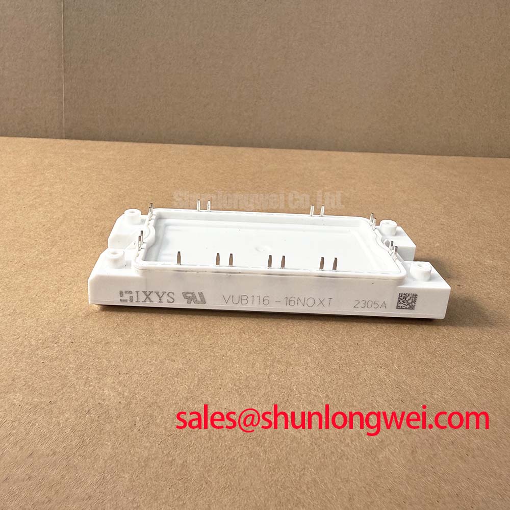
With the cabinet isolated and discharged, first compare the installed unit’s terminal layout, PWS E housing condition, mounting face, and nameplate ratings against the required VUO121-16NO1 electrical boundary before releasing any busbar hardware. This IXYS bridge rectifier is specified at 1600 V VRRM, 121 A IdAV at TC = 105°C, and a maximum 1.12 V forward voltage drop at IF = 150 A. Its 3000 V RMS isolation voltage and PWS E package are official datasheet specifications that must be preserved when assessing an in place replacement.
| Technical parameter | Official specification | Integration relevance |
|---|---|---|
| Maximum repetitive peak reverse voltage | 1600 V | Voltage boundary for repetitive reverse blocking duty |
| Average forward current | 121 A at TC = 105°C | Continuous current rating under the stated case temperature condition |
| Maximum forward voltage drop | 1.12 V at IF = 150 A | Conduction loss input for thermal assessment |
| Isolation voltage | 3000 V RMS | Specified isolation withstand level for the module |
| Package | PWS E | Mechanical interface for terminal and heatsink compatibility review |
Inspect the primary side before treating the rectifier as the isolated fault source. A bridge rectifier can be electrically intact while upstream surge protection, a line fuse, an input contactor, or a loose terminal connection has already altered the stress imposed on it. With all energy sources secured, examine the PWS E body for cracking, displaced hardware, heat discoloration at busbar interfaces, and evidence that the mounting surface has lost flat contact. These observations do not establish root cause on their own, but they determine whether controlled electrical checks are appropriate.
The 1600 V VRRM rating is the official repetitive reverse voltage limit for VUO121-16NO1. In equipment connected to a 480 V AC line, this rating provides the stated reverse voltage headroom, yet it does not eliminate the need to inspect the installed transient control network. Primary spark gaps, metal oxide varistors, and RC snubber arrangements are system level protection elements. Their selection must account for the supply arrangement, expected surge environment, wiring geometry, upstream protective devices, and the verified peak voltage seen at the rectifier terminals during operation.
IEC 61000-4-5 testing is a system immunity framework, not a compliance claim for this individual bridge rectifier. Design Consideration: review the complete cabinet protection path, including incoming protective devices, grounding conductors, conductor routing, surge suppressors, and the physical separation between high energy AC conductors and control wiring. A varistor that is thermally damaged, disconnected, or incorrectly installed can leave the rectifier exposed to a different transient condition than the original equipment design anticipated.
Where a fuse coordination table is available from the equipment manufacturer, maintenance personnel should compare its protected circuit designation with the actual installed fuse and rectifier position. The official specifications supplied for VUO121-16NO1 do not establish an I2t limit, a fuse part number, or a surge energy rating. Those values must therefore remain system determined rather than inferred from the 121 A average current rating. A replacement assessment should also confirm busbar width, terminal spacing, conductor orientation, and clearance to adjacent live hardware after tightening.
Field Alert: Isolate and discharge the DC link before disturbing rectifier terminals, then tighten mounting and electrical hardware only to the equipment manufacturer’s specified torque for the installed fastener and conductor stack.
The 3000 V RMS isolation voltage is an official specification, but it is not a blanket statement about the completed panel’s creepage distance, clearance, grounding scheme, or insulation coordination. Design Consideration: contamination, moisture, conductive dust, damaged barriers, and altered wiring routes can all change the cabinet level insulation condition. Verify the original equipment’s physical separation and protective covers before re energizing the assembly.
VUO121-16NO1 Thermal Electrical Optimization: Non Repetitive Surge On State Current Practical Tuning
Do not assign a non repetitive surge current capability to VUO121-16NO1 from its normal current rating. The supplied official data identifies 121 A IdAV at TC = 105°C, which describes average forward current under a defined case temperature condition. It does not provide an ITSM value, half cycle duration, starting junction temperature, or recovery condition. These missing parameters are material to any surge evaluation and must be taken from the applicable official manufacturer documentation or the original equipment service data.
For a service investigation, start with conditions that can create abnormal inrush or repeated high current events. Check input contactor operation, precharge equipment where fitted, charged capacitor banks, transformer energization sequence, capacitor switching logic, and the condition of the line side fuse. In a grid tied static var compensator or thyristor switched capacitor installation, the rectifier may be evaluated within an auxiliary supply or control power path, subject to the actual schematic and installed topology. It should not be assumed to occupy a particular power path merely from the product category.
Thermal assessment begins with the one value that is available. At a specified 1.12 V maximum VF at IF = 150 A, forward voltage contributes to conduction loss whenever current passes through the relevant diode path. Actual heating depends on current waveform, conduction duration, ambient conditions, heatsink performance, airflow, adjacent heat sources, and thermal interface quality. Engineering Recommendation: capture case temperature and the actual current waveform under the equipment’s operating state, then compare the evidence with the original thermal design limits. A clamp meter alone can miss waveform shape and transient loading.
The enclosure also contributes to thermal behavior. Heat exchange between surfaces and the surrounding enclosure is influenced by temperature and exposed area; the physical basis is described by the Stefan Boltzmann law for radiative heat exchange. This reference describes a general thermal mechanism, not a performance rating for VUO121-16NO1. Restricted airflow, blocked filters, or an enclosure change can alter the installed operating condition even when the rectifier and heatsink remain unchanged.
When repeated fuse operation or thermal discoloration is present, avoid attempting to restore service by increasing fuse capacity without a verified coordination study. A larger fuse can change the fault energy delivered to the rectifier, wiring, and capacitor bank. The correct response is to identify the protected branch, verify the original fuse characteristics, inspect the connected load for a short circuit, and establish whether the line event is transient, repetitive, or sustained. The final protective device selection belongs to the system design and maintenance authority.
VUO121-16NO1 Thermal Electrical Optimization: Short Circuit Withstand Limits and Coordination Practical Tuning
A cold resistance measurement can help identify an obvious failed bridge path, but it cannot certify short circuit robustness. With the bridge removed or isolated according to the equipment procedure, use diode test measurements across the relevant terminals and compare the directional response with a known good unit, the official connection diagram, or the equipment schematic. A low resistance in both directions, an open response where a diode path is expected, or inconsistent readings between comparable paths may justify further investigation. Meter readings are influenced by test current, probe contact, parallel circuitry, and terminal contamination.
The available official parameter set does not specify a short circuit withstand time, fuse clearing I2t, diode surge current, or fault energy capability for VUO121-16NO1. It would be unsafe to derive such limits from the 1600 V voltage rating, 121 A average current rating, or package appearance. Engineering Recommendation: obtain the equipment’s fuse coordination documentation and the rectifier manufacturer’s relevant surge and fault data before deciding whether a fuse characteristic is compatible with the installation.
In a dead short investigation, preserve evidence before replacing parts. Record fuse markings, conductor damage, switching positions, capacitor condition, contactor state, and any alarm history available from the equipment controller. Then isolate branches methodically. A failed bridge can be a consequence of a downstream fault, a line event, a degraded thermal interface, or an incorrect connection. Conversely, a shorted bridge can create secondary evidence at fuses and busbars. Treating one visible damaged part as the sole origin can lead to an immediate repeat failure after commissioning.
For topologies containing active power conversion stages, rectification paths must be understood from the actual circuit diagram. The Vienna rectifier three phase active power factor correction topology is a useful industry reference for understanding that rectifier behavior depends on circuit topology and switching control. It is not evidence that VUO121-16NO1 is specified for a Vienna rectifier, an SVC main power stage, or any particular switching configuration.
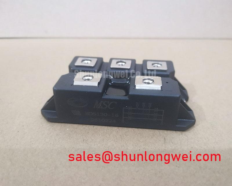
Where the original part cannot be retained, mechanical and electrical equivalence must be assessed together. The proposed device must match the circuit function, terminal arrangement, reverse voltage boundary, continuous current requirement, isolation requirement, package mounting geometry, and thermal interface assumptions. The SKD82/18 is a separate rectifier product that engineers may review as part of a documented cross reference exercise. Its suitability cannot be presumed from a similar category or a broadly comparable voltage class.
Field Diagnostics & Commissioning: Junction to Heatsink Heat Dissipation in VUO121-16NO1 Topologies
Before applying power, clean the heatsink contact surface and inspect it under direct light for burrs, corrosion, embedded debris, and distortion. The PWS E package must sit evenly against the prepared mounting plane. Apply the thermal interface material in accordance with the equipment manufacturer’s process, then secure the device in the prescribed tightening sequence. The supplied official specifications identify the package and electrical ratings, but they do not provide a mounting torque, thermal resistance value, thermal paste thickness, or heatsink flatness requirement. These installation details must come from the applicable mechanical documentation.
Uneven contact pressure can create local thermal resistance, while excessive force can damage the package or distort the interface. Design Consideration: use the original mounting hardware and verify that washers, insulating parts, busbars, and terminal lugs return to their documented positions. Do not allow a rigid busbar to pull the rectifier body out of plane during final tightening. After assembly, inspect whether the cable or busbar routing transfers mechanical load into the terminals as vibration and thermal cycling occur.
During controlled commissioning, verify the AC input condition, DC output behavior, protective device status, and case temperature trend using the original test points and safety procedure. Any unexpected ripple, asymmetric diode path response, abnormal heating, or repeated protective action should be investigated against the complete circuit rather than attributed solely to the bridge. System integrators should verify peak voltage margins against the DC link and measured switching or line transients during controlled tests.
Control displays and status panels can assist diagnosis but should remain a separate fault domain from the rectifier itself. For technicians tracing an industrial HMI issue that occurs alongside a power conversion fault, The Ultimate Guide to Industrial TFT LCD Technology provides useful context on display integration and common panel level checks. Confirm supply rails, signal continuity, grounding, and event logs before linking a display symptom to power rectification behavior.